Do you have a question about the Haier C2FE636CWJRU and is the answer not in the manual?
Service guidelines for electrical safety, insulation, and static discharge prevention.
Contains warnings about electrical shock, moisture, ESD, and lead-free solder.
Explains the use of icons (Note, Caution, Warning, Reference) within the manual.
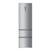
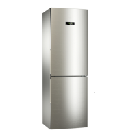
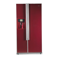
Detailed technical specifications and features for various refrigerator models.
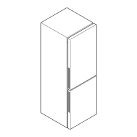
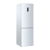
Illustrates the exterior components and layout of refrigerator models.
Highlights key features like appearance, frequency control, cooling functions, and LED display.
Step-by-step instructions for removing and replacing refrigerator and freezer doors.
Guidance on leveling the refrigerator using adjustable feet for stability.
Instructions for defrosting, cleaning, and general care of the refrigerator.
Step-by-step guide to disassemble the upper and bottom door bodies of the freezer.
Instructions for safely removing the display screen assembly.
Steps for disassembling air ducts in the refrigerating and chiller chambers.
Illustrates and lists components for the compressor chamber assembly.
Instructions for disassembling the heating wire used in the defrosting system.
Identifies controls and displays on the refrigerator's panel.
Guide to setting refrigerator and freezer temperatures using control panel keys.
Method to enter malfunction check mode and display sensor positions.
Describes the control principle of the fan cooling system based on sensors.
Briefly mentions the ice maker system.
Explains the automatic defrosting cycles and conditions.
Describes the control principle of the fan cooling system based on sensors.
Briefly mentions the ice maker system.
Explains the automatic defrosting cycles and conditions.
Discusses the role and control of the electromagnetic valve.
Diagram illustrating the refrigeration system's flow path with component labels.
Shows a 3D representation of the refrigeration system's layout.
Illustrates the air circulation paths within the refrigerator compartments.
Indicates the water supply path, noted as 'None' for these models.
A simplified electrical schematic showing major components and their connections.
Detailed wiring diagram of the main control printed circuit board.
Procedure to enter and perform self-test modes for cooling, defrosting, and operation.
Provides the PCB diagram for checking connections and components.
Details PCB photos and connection technical data for troubleshooting.
Addresses symptoms like frozen food and lack of defrosting, with check and solution steps.
Addresses issues like no display, no start, poor freezing, and loud noise.
| Brand | Haier |
|---|---|
| Model | C2FE636CWJRU |
| Category | Refrigerator |
| Type | Freestanding |
| Appliance placement | Freestanding |
| Product colour | White |
| Energy Class | A+ |
| Annual energy consumption | 325 kWh |
| Cooling Technology | No Frost |
| Noise Level | 39 dB |
| Number of Doors | 2 |
| Door hinge | Right |
| Refrigerant | R600a |
| Freezing capacity | 12 kg/24h |
| Star rating | 4* |
| Multi-Airflow system (fridge) | Yes |
| Lamp type | LED |
| Width | 595 mm |
| Ice Maker | No |
| Water Dispenser | No |