Do you have a question about the Haier C2F636CWRG and is the answer not in the manual?
Detailed illustration and material list for the compressor chamber components.
How to set temperatures and activate various cooling and freezing functions.
How to enter diagnostic mode and interpret error codes and sensor readings.
Visual guide showing the physical placement of various temperature sensors within the appliance.
Detailed explanation of the automatic defrost cycle logic and conditions.
Diagram illustrating the path of refrigerant through the cooling system.
Detailed circuit diagram of the main control printed circuit board.
Guide to performing self-test modes for diagnosing appliance functions.
Procedures for checking the main control board and its connections.
Common issues, symptoms, and troubleshooting steps for refrigerator malfunctions.
| Appliance placement | Freestanding |
|---|---|
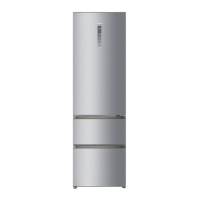
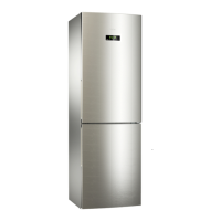
| Product colour | Stainless steel |
| Built-in display | Yes |
| Display type | LED |
| Control type | Touch |
| Freezing capacity | 12 kg/24h |
| Energy efficiency class | A++ |
| Width | 595 mm |
| Number of Doors | 2 |
| Color | Stainless steel |
| Shelves Material | Glass |
| Ice Maker | No |
| Reversible Door | Yes |
| Climate Class | SN-T |
| Storage time during power failure | 16 hours |
| Total Capacity | 336 L |