15
Installation
3. Address Code Setting ( SW401)
The former four digits of the eight-digit code switch are for module address setting, and the latter four for
unit mode and capacity setting. The unit mode and capacity codes have been set in delivery, and they
are unchangeable. The unit address codes default to 0N, 0N, 0N and 0N (for master unit), and in
delivery, the codes default to 0N, 0N, 0N and 0N.
The former four digits are available for module address:
Address No. SW1 SW2 SW3 SW4
0 ON ON ON ON
1 ON ON ON OFF
2 ON ON OFF ON
3 ON ON OFF OFF
4 ON OFF ON ON
5 ON OFF ON OFF
6 ON OFF OFF ON
7 ON OFF OFF OFF
8 OFF ON ON ON
9 OFF ON ON OFF
10 OFF ON OFF ON
11 OFF ON OFF OFF
12 OFF OFF ON ON
13 OFF OFF ON OFF
14 OFF OFF OFF ON
15 OFF OFF OFF OFF
Note:
(1) There is no same address code in one
system.
(2) The above address codes must be set by
professionals.
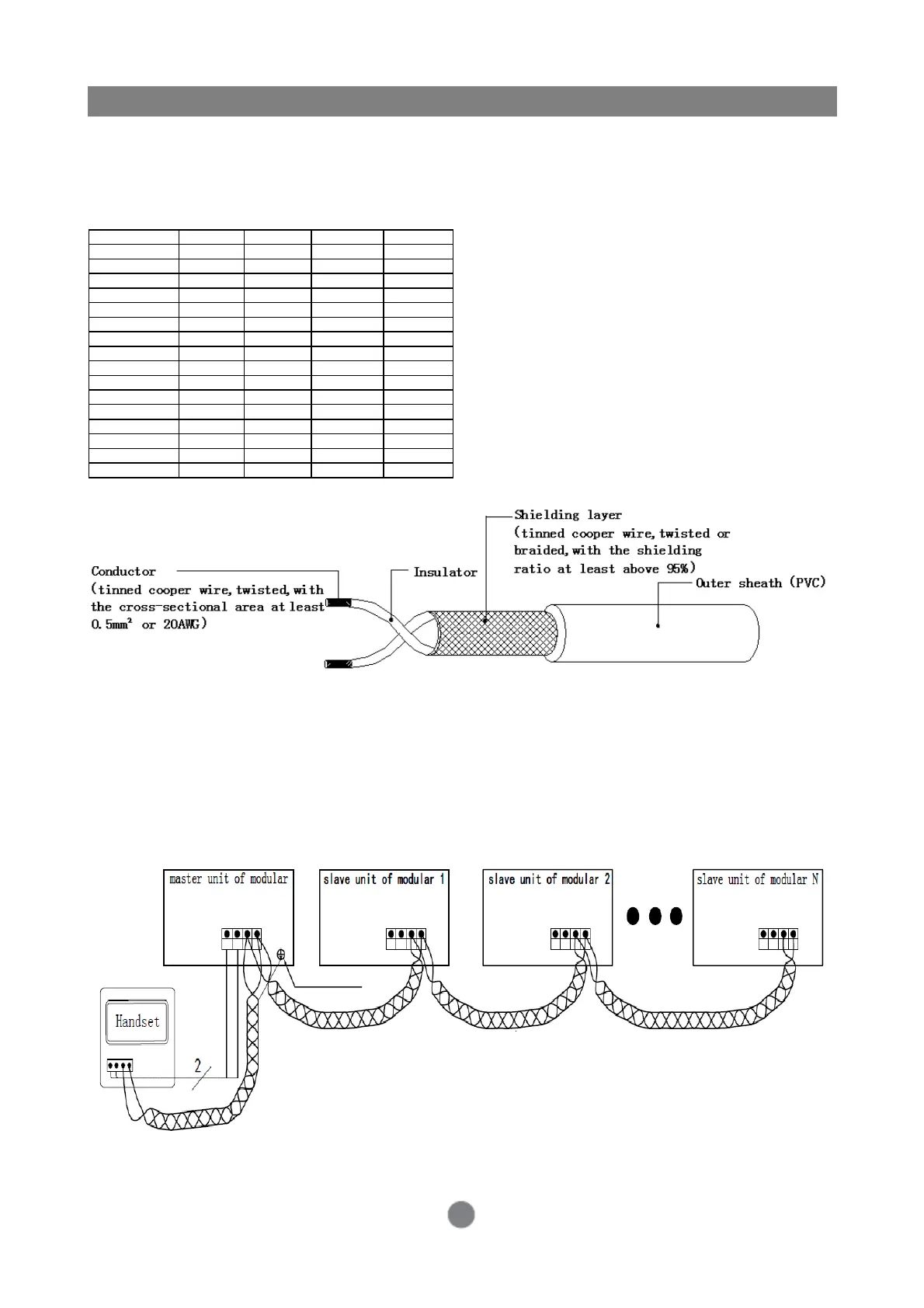
4. Requirements for Communication Wires
Description:
1. The network connecting wires with compact shielding layer and small lay of twisted conductors shall
be selected to the greatest extent.
2. Refer to UL2547 or UL2791 wire standards.
3. The length of control wire shall not exceed 1000 m.
4. The control wire routing must be more than 200 mm away from the heavy-current installations.
5. Connection of Communication Wires
ON
RS485-A
RS485-A
RS485-A
+12V GND A1 B1
CN19
+12V GND A1 B1
RS485-A
CN19
+12V GND A1 B1+12V GND A1 B1
CN19
CN19
output wiring terminal
output wiring terminal
output wiring terminal
output wiring terminal
+12V GND A1 B1