EasyManua.ls Logo

Haier GE Appliances AW24TL2HFA User Manual

Haier GE Appliances AW24TL2HFA
77 pages
To Next Page IconTo Next Page
Page #1 background imageLoading...
Page #1 background image
Ductless Split Heat Pump
Service Manual
Design may vary by model number.
Please read this manual before installing this product.
Keep this user manual for future reference.
PAGE 1
Safety Precautions/Introduction ................................................................................................. 3
Outdoor Unit Controls and Components ..................................................................................... 7
Indoor Unit Controls and Components ...................................................................................... 13
Sequence of Operation .............................................................................................................. 19
System Specications ............................................................................................................... 28
Error Codes and Troubleshooting .............................................................................................. 29
Reference Information .............................................................................................................. 62
Indoor
AW24TL2HFA
AW30TL2HFA
AW36TL2HFA
ASYW24TRDFA
ASYW30TRDFA
ASYW36TRDFA
Outdoor
1U24TL2HFA
1U3036TL2HFA
ASH124TRDFA
ASH3036TRDFA
Table of Contents

Table of Contents

Question and Answer IconNeed help?

Do you have a question about the Haier GE Appliances AW24TL2HFA and is the answer not in the manual?

Haier GE Appliances AW24TL2HFA Specifications

General IconGeneral
BrandHaier
ModelGE Appliances AW24TL2HFA
CategoryHeat Pump
LanguageEnglish

Summary

Safety Precautions and Introduction

Safety Precautions

Details important safety warnings and cautions for installation and operation.

System Overview and Fundamentals

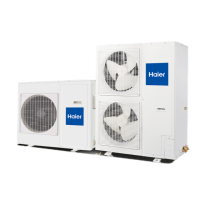
Explains system components, operation, and basic principles.

Outdoor Unit Controls and Components

Outdoor Unit Overview and Identification

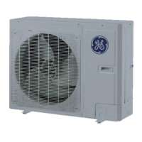
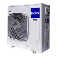
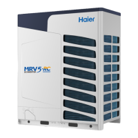
Provides an overview of the outdoor unit and identifies its main components.

Outdoor Unit Control Boards and Wiring

Details the outdoor control and module PCBs and their connections.

Key Outdoor Unit Components

Describes the terminal block, compressor, fan motor, and power factor reactor.

Outdoor Unit Sensors

Details various temperature sensors and the oil separator in the outdoor unit.

Refrigerant Flow Control Components

Explains the function of the 4-way valve, accumulator, and EEV.

Indoor Unit Controls and Components

Indoor Unit Overview and Identification

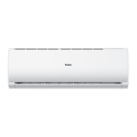
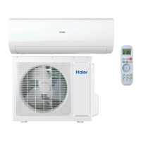
Introduces the indoor unit and identifies its main components.

Indoor Control Board and DIP Switches

Details the indoor unit's control board, connectors, and DIP switches.

Indoor Unit Terminal Block, Display, and Sensors

Covers the indoor unit's terminal block, status display, and sensors.

Indoor Unit Motors and Emergency Button

Describes the fan motor, louver motors, and the emergency operation button.

Sequence of Operation

System Power and Cooling Operation

Explains system power supply and the sequence of operation during cooling mode.

Heating, Defrost, and Freeze Protection

Details heating mode, defrost cycles, and freeze protection functions.

Auto, Dry Modes, and Protections

Covers auto, dry operation modes and critical protection functions.

Special Functions and Smart Features

Explains Auto Restart, Timed Defrost, SmartHQ, and Estar6.1 features.

System Specifications

Model and Performance Specifications

Presents detailed technical data, capacity, and performance metrics for models.

Error Codes and Troubleshooting

Initial Diagnostic Flowcharts

Provides initial checks and flowcharts for outdoor and indoor unit issues.

Specific Error Code Troubleshooting

Guides through diagnosing and resolving common error codes like IPM, compressor, and communication faults.

Sensor and Motor Fault Diagnosis

Details troubleshooting for sensor failures, fan motor faults, and overheat protection.

Compressor, Communication, and EEPROM Errors

Groups compressor sync, EEPROM, and communication error troubleshooting.

Operational Protection and Failure Codes

Groups coil frost protection, indoor fan motor failure, and other operational issues.

Component Testing Procedures

Outlines methods to test outdoor and indoor unit components like sensors, motors, and coils.

Reference Information

Wiring Diagrams and Schematics

Provides detailed wiring diagrams for outdoor and indoor units.

Sensor Resistance and Specification Tables

Compiles sensor resistance values and operational specifications.

Related product manuals