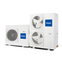
Do you have a question about the Haier AU082FYCRA(HW) and is the answer not in the manual?
Describes materials and basic construction of the unit's housing.
Details the design and material of the air cooling coils for efficient heat exchange.
Explains the type and features of the axial-flow fan motor for heat exchange.
Describes the integrated hydraulic components like heat exchangers and pumps.
Details the electrical panel construction and compliance with standards.
Specifies operating limits for delivery and leaving conditions.
Details how fouling factors affect performance data.
Details compliance with EU directives and refrigerant usage guidelines.
Outlines critical safety precautions for operation and installation.
Covers fixing, inspection, and related procedures.
Details maintenance principles, components, and environment.
Covers safe methods for lifting, hoisting, and manually moving the unit.
Guidelines for selecting an appropriate and safe installation location.
Specifies required clearances and spaces for installation and maintenance.
Details precautions to be taken during the installation process.
Instructions for unit drainage and hydraulic circuit requirements.
Settings for control type, model selection, and power options.
Settings for heat exchange type, control mode, and running modes.
Steps for preparing and starting the unit for the first time.
Explains operating modes, alarms, and fan/pump controls.
Covers routine, extraordinary maintenance, chemical washing, and refrigerant handling.
Describes the display layout and icons on the wired controller.
Explains the function of each button and system icon.
Details basic and special function operations for the controller.
Covers week/clock settings, dip switches, and wiring instructions.
Lists error codes, their definitions, and notes for troubleshooting.
Details standby codes, their associated reasons, and notes.
Flowchart for diagnosing and resolving temperature sensor issues.
Flowchart for diagnosing and resolving water flow protection issues.
Flowcharts for diagnosing and resolving high/low pressure sensor failures.
Flowchart for diagnosing and resolving high pressure switch failures.
| Heating Capacity | 2.5 kW |
|---|---|
| Energy Efficiency Ratio (EER) / Cooling | 3.21 |
| Seasonal Energy Efficiency Ratio (SEER) | 6.1 |
| Refrigerant | R32 |
| Weight (Indoor Unit) | 9 kg |
| Cooling energy efficiency class | A++ |
| Heating energy efficiency class | A+ |
| Power Supply | 220-240V, 50Hz |
| Noise Level (Outdoor) | 50 dB |


