Do you have a question about the Haier GE APPLIANCES AUH2436ZGDA and is the answer not in the manual?
Essential safety rules for performing maintenance procedures and precautions.
Essential safety rules for operating the heat pump unit.
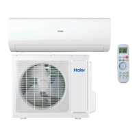
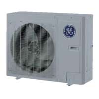
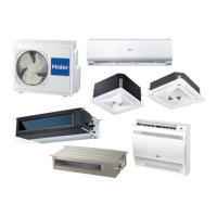
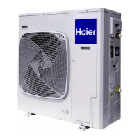
Details of available outdoor and indoor units.
Flowcharts detailing cooling and heating operational logic.
Details on compressor, EXV, fan, and valve control modes.
Configuration options like capacity and defrost settings.
How to set operating mode and indoor fan speed via DIP switches.
Procedures for forced defrost, recovery, and operation.
Electrical diagrams for outdoor and indoor units.
Component layouts for indoor and outdoor unit boards.
Procedures for testing IPM and PFC modules.
List of error codes and their associated issues.
Troubleshooting for major system protection errors like E1, E3, E4.
Troubleshooting for chip, overload, IPM, fan, and driver errors.
Troubleshooting for sensor, AC/Bus voltage, communication, and charge loop errors.
Common operational issues not tied to specific error codes.
Refrigerant system schematic and evacuation procedures.
Steps for charging refrigerant into the system.
Diagnosis, replacement, and detachment of the compressor.
Procedures for drive module, ODU components, panels, and valves.
Procedures for IDU electric box, fan motor, coil, drain pan, and filter.
Visual breakdowns and parts lists for ODU and IDU.
Resistance and voltage data for temperature sensors.
Temperature and pressure data for R-410A refrigerant.
Airflow data for various indoor unit models.
List of tools needed for operation and maintenance.