Do you have a question about the Haier GE UltraFresh GFD55ESSN and is the answer not in the manual?
Basic steps for operating the dryer, including cleaning the lint filter and starting a cycle.
Information on connecting the dryer to a smartphone via Wi-Fi for remote control and notifications.
Explanation of the dryer's display, Wi-Fi indicator, control lock, and vent/filter status lights.
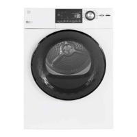
Diagram identifying major components visible from the top of the dryer.
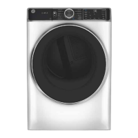
Diagram identifying major components visible from the front of the dryer.
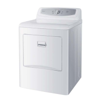
Identification of components located at the bottom of gas dryer models.
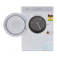
Identification of components located at the bottom of electric dryer models.
Details on the UI board's function and connectivity.
Details on the Wi-Fi board's function and connectivity.
Instructions for accessing the control panel and the RJ45 connector.
Steps and warnings for reversing the dryer door swing direction.
Instructions for removing the strike plate and the main door assembly.
Steps to disassemble the inner door frame from the outer door.
Instructions for reinstalling the inner door frame and securing it with screws.
Final steps to reattach the door assembly and strike plate.
Procedure for replacing the misting nozzle, including tool requirements and mesh screen handling.
Procedure for diagnosing the misting/steam valve using resistance checks.
Steps to remove the water valve from the dryer assembly.
Detailed instructions for removing the dryer's front panel.
Steps to remove the front drum support that holds the drum in place.
Steps to diagnose issues with the drum lamp assembly using voltage checks.
Procedure for removing the dryer's internal sensor rods.
Steps to diagnose the electric heater assembly using resistance checks and relay identification.
Description of the gas valve's coils and their function in gas dryers.
Steps to remove the radiant sensor (flame detector) from the combustion chamber.
Instructions for removing the blower wheel, including nut rotation and tool usage.
Description of the standard vent motor's shaft and attachments.
Description of the long vent motor's speed increaser pulley system.
Steps to remove the inlet thermistor, including its location and resistance values.
Steps to remove the outlet thermistor, including its location and resistance values.
Instructions for diagnosing and removing the user interface board.
Guide for consumers to read fault codes from the dryer.
Instructions for entering and navigating the dryer's service mode for testing.
| Appliance Category | Dryer |
|---|---|
| Brand | GE |
| Model | GFD55ESSN |
| Type | Electric |
| Capacity | 7.8 cu. ft. |
| Width | 27 inches |
| Energy Star Certified | Yes |
| Control Type | Electronic |
| Ventless | No |
| Steam | Yes |
| Smart | Yes |
| Wrinkle Care Option | Yes |
| Depth | 32 in |