(CN2)
ACL
(CN3)
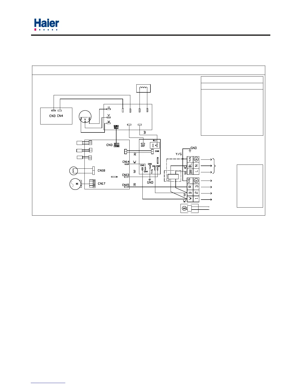
OUTDOOR UNIT WIRING DIAGRAM
REACTOR
NOTES:
THE PART OF DOTTED IS OPTIONAL
4-WAY VALVE
COMP.TEMP.SENSOR
AMBIENT TEMP.SENSOR
DEFROST
OUTDOOR PCB
CN11
CN10
CN9
FAN MOTOR
TEMP.SENSOR
T3.15A/250VAC
FUSE
CAP BOARD
OR
R
W
B
BL
COMPRESSOR
M
R(Y)
SPDU
(IPDU)
(CN4)
ACN
(CN1)
W
(CN5)
P(+)
(CN6)
N(-) RI
DC MOTOR
TERMINAL BLOCK
FILTER
FUSE
T25A/250VAC
TO INDOOR
POWER SUPPLY
R: RED
Y/G:YELLOW
/GREEN
BL:BLUE
OR:ORANGE
W: WHITE
Y:YELLOW
B: BLACK
CAUTION
The capacitor retains high
voltage even after the plug-off.
For your safety, be sure to wait
at least 5 minutes. after plug
off and use a tester to confirm
the voltage between connector
CN3 and CN4 is less than DC 10V
before start servicing.
DON'T TOUCH CAPACITOR, EVEN AFTER
PLUG-OFF ( DANGER OF ELECTRIC SHOCK)
R(Y)
RO
0010556830
WARNING
Wiring diagram of
outdoor unit
Model: HSU-22H03/R2(DB)Domestic Air Conditioner
32
 Loading...