37
8
1. Remove all packaging materials.
2. Inspect standard accessories shipped with the unit
Inspect the accessories against packing list. Should
there be any discrepancy, contact the after-sale
department.
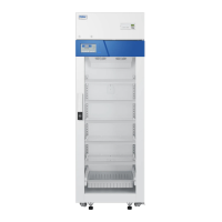
3. Installation
Leave a minimum space of 10 cm around the
refrigerator for ventilation and heat dissipation.
(Pic.2).
4. Adjust the leveling leg
Rotate the leveling legs with a wrench in clockwise
to extend them out and secure them onto the ground.
This is to make sure the refrigerator does not move
during operation.(Pic.3).
Preparation before usage
Leveling legs
Downward
upward
> 30cm from the top
> 10cm from
the back
> 10cm from
the left
> 10cm from
the right
For safety reason, the equipment of
HYC-890/940/940F is situated on a wooden
pallet and secured by metal brackets. Please
remove the screws and place the metal
brackets under the unit.(Pic.1).
Pic.1
Pic.2
Pic.3
Forklift or specialty lifting equipment should be
used to remove the unit off the pallet. Forklift
should reach the bottom of the wood pallet for
lifting.
The unit should not be tilted at an angle of
more than 45 degree.
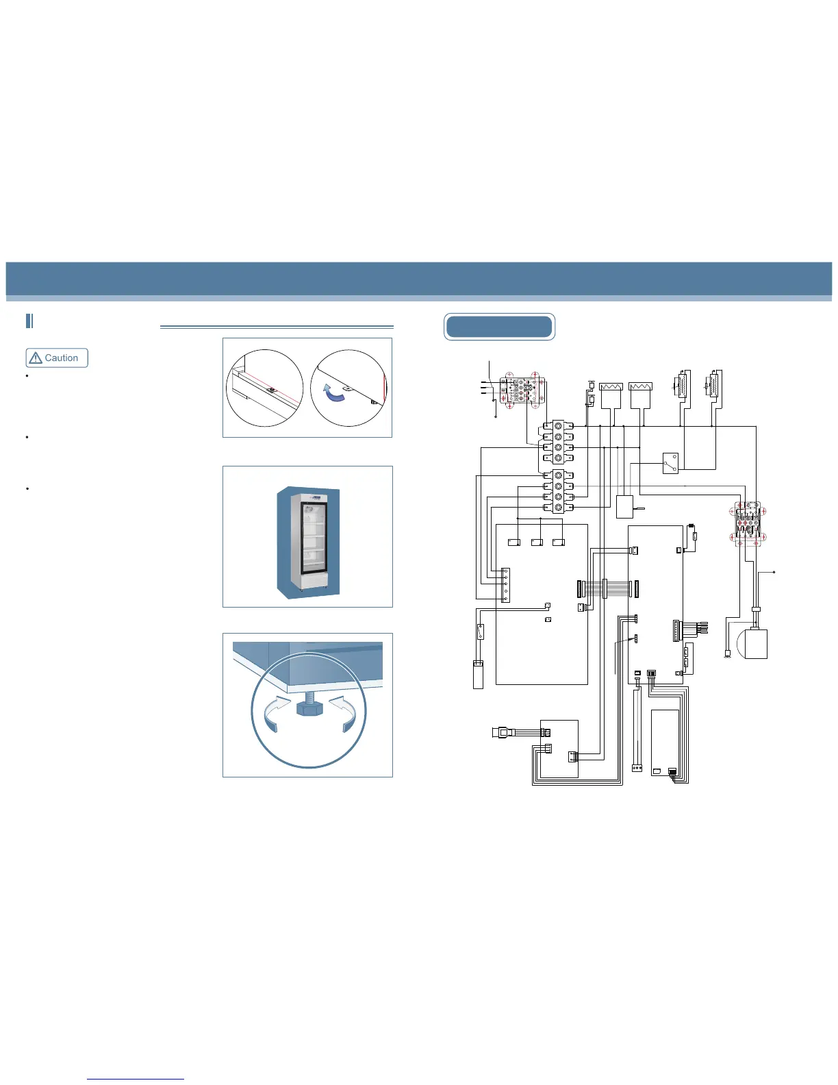
Circuit diagram(HYC-890)
CN2
Compressor
Defrosting
heating
strip
CN2
CN1
CN3
CN11
BT1
BAT+
BAT-
Main control panel
CN5
Display panel
CN2
CN3
Sensor
Alarm
Defrosting
Control
Lower temperature
Upper temperature
VCC
GND
Heating strip
at the front vertical beam
CN1
t
Door heating strip
Door heating transformer
CN1
16V
GND
16V
GND
CN7
Battery switch
Lamp switch
Power panel
N
L
FAN
HTR
NC
NC
NC
NO
NO
NO
K3
K7
K4
CN5
CN4
CN4
USB
PRINT
Printer communication interface
GND
+12V
CN6
NO
COM
NC
NO
COM
NC
Remote alarm port
Power wire
Junction
box
1
L
N
2
L
N
t
Door heating strip
Door heating transformer
Terminal connected to the
compressor bottom board
C
H
L
High temperature
prevention
thermostat
L
N
E
1
L
N
2
L
N
Terminal connected
to the compressor
bottom board
Internal fan
LED lamp set
Terminal connected
to the roof of cabinet
Cooling fan
C
N
L
Electronic
controller
Sensor
CN1
J5
L
N
CN2
USB port
USB panel
door
Door switch
 Loading...