38
Performance of the refrigerator is degraded if the operational conditions are
beyond the specifications mentioned above.
Ambient temperature: 16 ℃ to 32 ℃, the range of 18 ℃ to 25 ℃ is optimal. Air conditioning
system is required as necessary.
Ambient humidity: below 85%RH(for HYC-260/360,the humidity should be less than 70%RH).
Avoid excessive dust.
Avoid mechanical vibration.
The refrigerator shall operate at an altitude lower than 2000m.
Input voltage: no greater than ±10% of rated voltage.
The unit should be installed indoors. Electric leakage or shock is possible if the
unit gets wet by rainwater.
The installation site shall meet following requirements for normal operation and best performance of
refrigerator:
Do not install the refrigerator in a narrow and confined space as heat may be trapped to increase
ambient temperature. Additionally, the unit should not be installed in a space where the entry door
way is low to prevent an easy maneuver of the unit for maintenance and operation.
The floor for the installation site should be solid and flat. It should also be well ventilated and free
from direct sunshine.
The power outlet for the refrigerator must be a dedicated power outlet. The power plug must be
plugged in to the outlet securely.
Do not twist or jam the power cord.
If the power cord needs to be extended, the cross section area of the conductor in the extended
line should be no less than 2 squared millimeters and no longer than 3 meter.
Inspect the operating voltage range before operation. If the voltage supply is unstable, install a
voltage stabilizer of 4000 W or greater to ensure the supply voltage is within 10% of the rated
voltage supply.
The refrigerator must be grounded reliably.
Check the integrity of the socket ground before power up. If it is not grounded appropriately,
repair the wiring before installing the unit.
Do not ground the refrigerator through gas lines, water lines, telephone lines, or lighting rods as
these devices may cause electric shock and danger.
Product Installation
Installation environment
Installation site
The power plug and outlet should be located in a place where they can be
accessed easily and immediately in case of an emergency. Air vents must be
free of obstruction.
The power plug can be accessed after installation to ensure the power line can
be pulled out in a timely manner in emergency cases. The air vent shall free from
barriers.
7
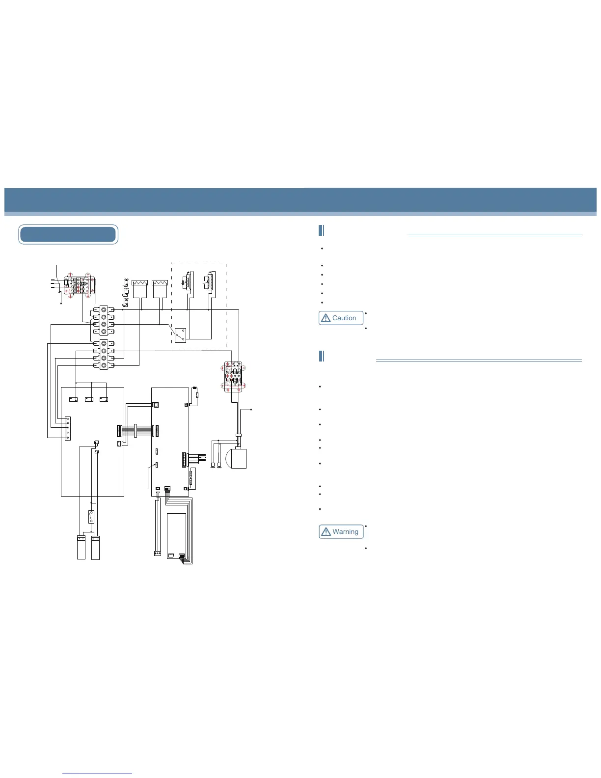
Circuit diagram(HYC-940/940F)
door
Door switch
CN2
Cooling fan
Compressor
Defrosting
heating
strip
CN2
CN1
CN3
CN11
BT1
BAT+
BAT-
Main control panel
CN5
Display panel
CN2
CN3
Sensor
Alarm
Defrosting
Control
Lower temperature
Upper temperature
VCC
GND
Heating strip
at the cabinet
outlet
CN1
t
Door heating strip
Door heating transformer
CN1
16V
GND
16V
GND
CN7
Battery switch
Lamp switch
Power panel
N
L
FAN
HTR
NC
NC
NC
NO
NO
NO
K3
K7
K4
CN5
CN4
CN4
USB
PRINT
Printer communication interface
GND
+12V
CN6
NO
COM
NC
NO
COM
NC
Remote alarm port
Power wire
Junction
box
1
L
N
2
L
N
t
Door heating strip
Door heating transformer
Terminal connected to the
compressor bottom board
C
H
L
High temperature
prevention
thermostat
L
N
E
1
L
N
2
L
N
Terminal connected
to the compressor
bottom board
Internal fan
LED lamp set
Terminal connected
to the roof of cabinet
LED lamp set
Cooling fan
Note: The content in the frame with dotted lines are not
applicable for products with the foaming door.
 Loading...