When the call for heat is satisfied the blower will continue to operate at a reduced rate for a
period of 3 minutes to remove all of the usable heat from the furnace while still maintaining
the plenum temperatures at a comfortable level.
ECM Motor Air Flow Selection
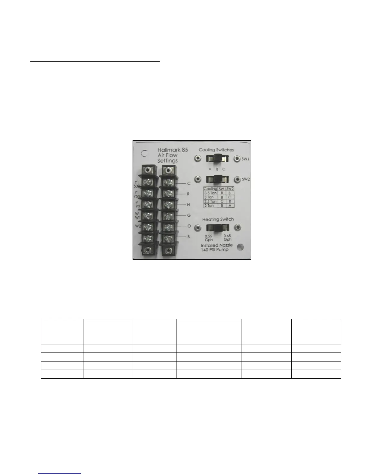
Air flow settings for both heating and cooling are made by setting the heating and the cooling airflow
DIP switches to the proper location. These DIP switches are located in the 4 x 4 junction box
mounted directly under the fan center relay. Do not change the air flow settings until the blower has
come to a complete stop. No change in air flow will occur unless the motor has been allowed to a
complete stop.
See figure below for the location of the heating and cooling DIP switches. Hallmark 85 shown as
typical.
Do not adjust the heating air flow below the firing rate of the furnace. The air flows for heating are
designed to give a 70
o
F to 75
o
F temperature rise.
Burner
Firing Rate
Heating Air
Flow
Cooling/
Heat Pump
Tonage
Air Flow
Y1-50%/Y1-75%
Air Flow
Y/Y2
Fan Only Air
Flow
0.65 GPH 975 CFM 2 400/600CFM 800 400 CFM
0.75 GPH 1175 CFM 2-1/2 500/750 CFM 1000 500 CFM
0.85 GPH 1275 CFM 3 600/900 CFM 1200 600 CFM
1.00 GPH 1500 CFM 4 800/1200 CFM 1600 800 CFM
10