75.5092.09 EN 20160623 Page 3 of 4
6 Battery Replacement
CAUTION: THERE IS A RISK OF EXPLOSION IF AN INCORRECT BATTERY TYPE IS USED.
DISPOSE OF USED BATTERIES ACCORDING TO ITS INSTRUCTIONS.
1 3 - VOLT TRANSMITTERS
1. Remove two screws from back of transmitter.
2. Separate housing and install a fresh 3-Volt (Type CR2032) battery making sure to observe proper polarity.
3. Reassemble housing and replace screws.
NOTE: Don’t throw used batteries away with the general trash. Discard per your local municipal laws and regulations.
2 9 - VOLT TRANSMITTER
1. Remove old battery.
2. Connect a fresh 9-Volt (Type 6LR61) battery making sure to observe proper polarity.
NOTE: Don’t throw used batteries away with the general trash. Discard per your local municipal laws and regulations.
7 FCC Compliance
• This Digital Transmitter complies with Part 15 of the FCC rules. Operation is subject to the following two conditions:
1) This device may not cause harmful interference and;
2) This device must accept any interference received including interference that may cause undesired operations.
a) This equipment has been tested and found to comply with the limits for a Class B digital device, pursuant to part 15 of the FCC
Rules. These limits are designed to provide a reasonable protection against harmful interference in a residential installation.
This equipment generates, uses and can radiate radio frequency energy and, if not installed and used in accordance with the
instruction, may cause harmful interference to radio communications. However, there is no guarantee that interference will not
occur in a particular installation. If this equipment does cause harmful interference to radio or television reception, which can be
determined by turning the equipment off and on, the user is encouraged to try to correct the interference by one or more of the
following measures:
• Reorient or relocate the receiving antenna.
• Increase the separation between the equipment and receiver.
• Connect the equipment into an outlet on a circuit different from that to which the receiver is connected.
• Consult the dealer or an experienced radio/ TV technician for help.
• This transmitter operates in the band 433.5- 434.5 MHz and is restricted to periodic transmissions of up to 5 seconds.
• Changes or modications not expressly approved by BEA, Inc. for compliance could void the user’s authority to operate the equipment.
• Devices authorized under these provisions shall be provided with a means for automatically limiting operation so that the duration
of each transmission shall not be greater than 60 seconds and be only permitted to re initiate an interrogation in the case of a
transmission error.
FCC ID#: G9B-10TD433HH4 IC ID#: 4680A-10TD433HH4
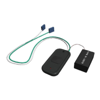
5 Wiring
Power VAC/DC Output
Label 12 - 24 12 - 24 Com. N.O. N.C.
Wire Color Red (+) Black (-) White Green Grey
Terminal 1 2 3 4 5
Description
Control or Transformer power Control Common Control Activation Typically not used
 Loading...