EasyManua.ls Logo

Halsey Taylor HydroBoost HTHB-HAC User Manual

Halsey Taylor HydroBoost HTHB-HAC
14 pages
To Next Page IconTo Next Page
Page #1 background imageLoading...
Page #1 background image
Page 1 1000004727 (Rev. A - 09/18)
HAC-HB*1C HAC-HB-NF-*1C
HTHB-HAC
Retrot Hydroboost
®
Bottle Filling Station
HTHB-HAC Bottle Fillers are among the easiest to install on the market today.
To insure you install these models easily and correctly, PLEASE READ THESE
SIMPLE INSTRUCTIONS BEFORE STARTING THE INSTALLATION. CHECK YOUR
INSTALLATION FOR COMPLIANCE WITH PLUMBING, ELECTRICAL, AND OTHER
APPLICABLE CODES. After installation, leave these instructions with the Fountain
for future reference.
IMPORTANT
THIS IS AN INDOOR APPLICATION ONLY.
ALL SERVICE TO BE PERFORMED BY AN
AUTHORIZED SERVICE PERSON.
IMPORTANT! INSTALLER PLEASE NOTE.
THE GROUNDING OF ELECTRICAL EQUIPMENT SUCH AS TELEPHONE, COMPUTERS, ETC. TO WATER LINES
IS A COMMON PROCEDURE. THIS GROUNDING MAY BE IN THE BUILDING OR MAY OCCUR AWAY FROM THE
BUILDING. THIS GROUNDING CAN CAUSE ELECTRICAL FEEDBACK INTO A FOUNTAIN, CREATING AN
ELECTROLYSIS WHICH CAUSES A METALLIC TASTE OR AN INCREASE IN THE METAL CONTENT OF THE WATER.
THIS CONDITION IS AVOIDABLE BY USING THE PROPER MATERIALS AS INDICATED. ANY DRAIN FITTINGS
PROVIDED BY THE INSTALLER SHOULD BE MADE OF PLASTIC TO ELECTRICALLY ISOLATE THE FOUNTAIN
FROM THE BUILDING PLUMBING SYSTEM. WE SUGGEST THAT THE BOTTLE FILLING STATION AND WATER
COOLER BE PROTECTED BY A GROUND FAULT CIRCUIT INTERRUPTER (GFCI).
INSTALLER
TOOLS REQUIRED
BUT NOT PROVIDED:
SAFETY GLASSES
GLOVES
ELECTRIC DRILL
3/4” WRENCH OR CRECENT
WRENCH
UTILITY KNIFE
TAPE MEASURE
PENCIL
5/32” ALLEN WRENCH
Installation and Use Manual
Question and Answer IconNeed help?

Do you have a question about the Halsey Taylor HydroBoost HTHB-HAC and is the answer not in the manual?

Halsey Taylor HydroBoost HTHB-HAC Specifications

General IconGeneral
BrandHalsey Taylor
ModelHydroBoost HTHB-HAC
CategoryWater Dispenser
LanguageEnglish

Summary

Filter Installation Procedures

Attach Port Fittings onto Filter Head

Insert 3/8" 90° Quick Connect elbow fitting into Superseal IN port.

Filter Head Mounting

Mount Filter Head Assembly

Mount filter head assembly into cooler on the inside of the left panel.

Connect Building Water Supply

Connect 3/8" tubing between filter inlet and water inlet.

Re-Plumbing Water Circuits (Non-Filter)

Re-Plumbing Water Circuits (With Filter)

Bottle Filler Installation Steps

Test Water Dispensing

Verify proper dispensing by testing sensor area.

Control Board Programming

Resetting the Filter Monitor

Depress program button to reset filter status.

Setting IR Sensor Range

Adjust range setting for IR sensor from 1 to 10.

Setting Unit Type

Set unit type to REFRIG or NON-RFRG.

Resetting Bottle Count

Depress program button to reset the bottle count to zero.

Setting Filter Capacity

Select filter capacity, either 3000GAL or 6000GAL.

Wiring Diagram and Parts

Wiring Diagram

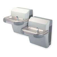
120 Volt wiring diagram for single & two level units.

Replacement Part Kits

List of available replacement part kits and their descriptions.

Related product manuals