15
Ignition Outputs
Ignition outputs must be connected directly to
an ignition module to control the ignition of the
vehicle.
Do not connect directly to a coil without an
internal or external ignition module as doing
this will damage the ECU.
The ECU ignition output produces a signal
between 12V and ground to control the ignition
module allowing the charging and firing of the
coil.
When not used for ignition, pins can be used as
generic Digital Pulsed Outputs (DPO) capable of
switching 3A to ground.
Specs:
• Software selectable global 12V or 5V
pull-up Voltage
• Individual software selectable 270R
pull-up Enable
• Flyback protected
• 3A sink current
• 10kHz switching speed
• Automatic overcurrent protection
• 0 to 27V voltage feedback
WARNING
Connecting the ECU to an ignition module
before setting the ignition firing edge correctly
may damage the module and coils, therefore it
is advised to disconnect the module or disable
the power to the ignition system until the unit
has been setup and configured.
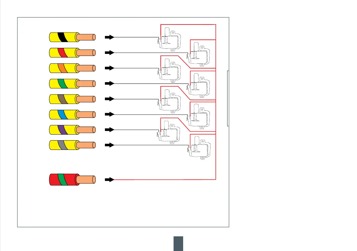
IGN1
IGN4
IGN2
IGN3
IGN5
IGN8
IGN6
IGN7
HCO
WIRING SHOWN
DIRECT FIRE IGNITION
WARNING
THECOILS DEPICTEDINTHISDIAGRAM
(HT-020102) .HAVE INTERNALIGNITORS
DO NOTCONNECT IGNITION OUTPUTS
DIRECTLY TO COILS UNLESS THEY
HAVE INTERNAL IGNITORS
TECU.HISWILLDAMAGE THE
PLEASE USEANEXTERNALIGNITOR FOR
.COILSWITHOUT INTERNAL IGNITORS
Example wiring connection
(Direct Fire Ignition wiring shown)
NOTE: The coils depicted in this diagram (HT-020102)
have internal ignitors. Do not connect ignition outputs
directly to coils unless they have internal ignitors.
This will damage the ECU. If your coils are without
internal ignitors you must use an external ignitor.
Ensure the High Current Output (8A or 25A) used to
power the ignition coils is capable of supplying the
required current.
 Loading...