18
Subject to change without notice
After the time base has deflected the trace from left to right,
the trace will be blanked so the retrace is invisible. The next
sweep will, however, not immediately start. Time is required to
perform internal switching, so the next start is delayed for the
so called hold off time, irrespective of the presence of triggers.
The hold off time can be extended from its minimum by a factor
of 10:1. Manipulation of the hold off time and thus of the time for
a complete sweep period from start to start can be useful e.g.
when data packets are to be displayed. It may seem that such
signals can not be triggered. The reason is that the possible
start of a new sweep does not coincide with the start of a data
packet, it may start anywhere, even before a data packet. By
varying the hold off time, a stable display will be achieved by
setting it so that the hold off ends just before the start of a data
packet. This is also handy with burst signals or non periodic
pulse trains.
A signal may be corrupted by noise or hf interference so a double
display will appear. Sometimes varying the trigger level cannot
prevent the double display but will only affect the apparent time
relationship between two signals. Here the variable hold off time
will help to arrive at a single display.
Sometimes a double display will appear when a pulse signal
contains pulses of slightly differing height requiring delicate
trigger level adjustment. Also here increasing the hold off time
will help.
Whenever the hold off time has been increased it should reset
to its minimum for other measurements, otherwise the bright-
ness will suffer as the sweep rep rate will not be maximum. The
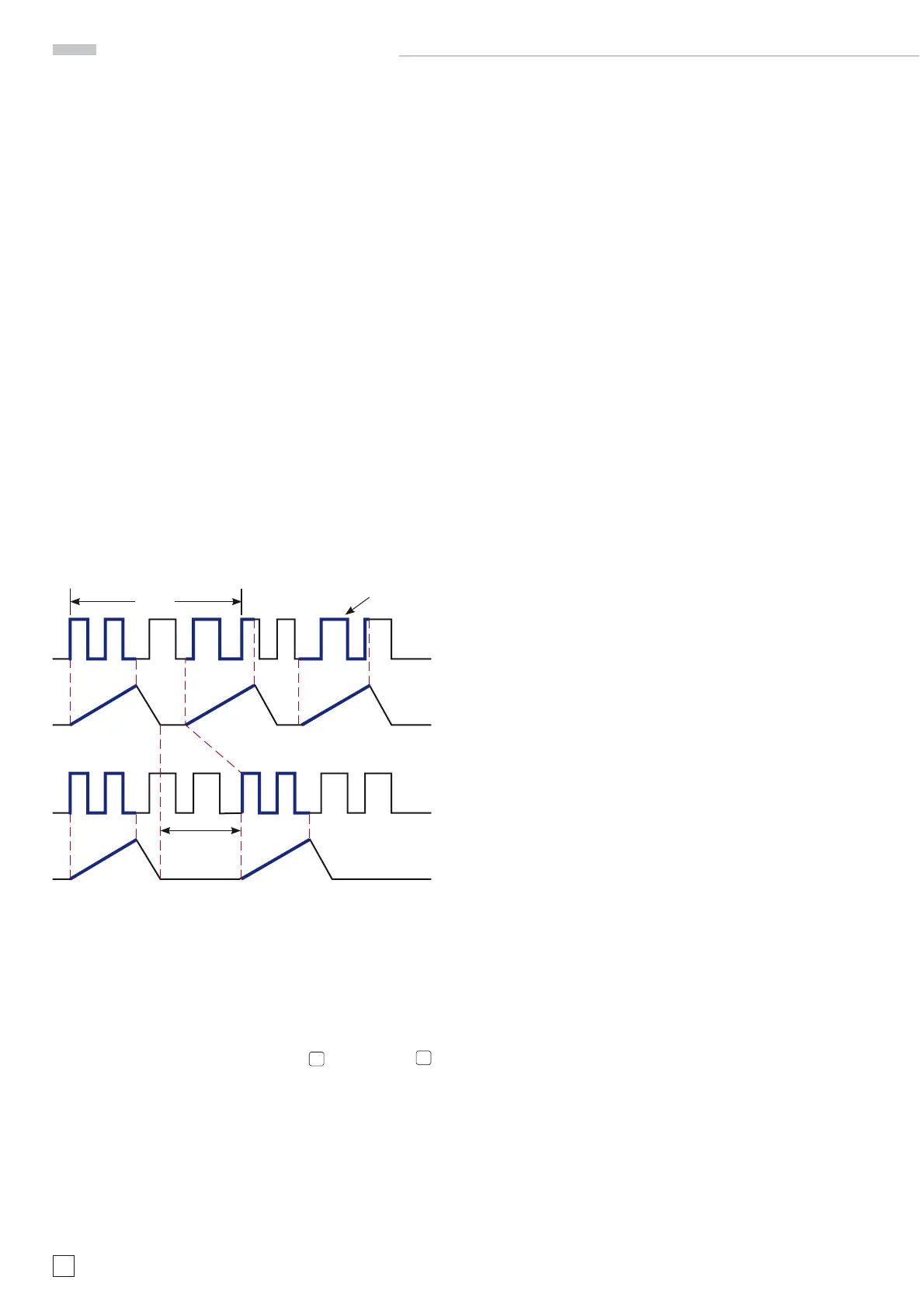
following pictures demonstrate the function of the hold off:
Fig. 1: Display with minimum hold off time (basic setting).
Double image, no stable display.
Fig. 2: By increasing the hold off a stable display is achieved.
Time base B (2
nd
time base). Delaying, Delayed
Sweep. Analog mode
Consult ”Controls and Readout“ HOR VAR
30
and TIME/DIV.
28
for specifi c information.
As was described in ”Triggering and time base“ a trigger will
start the time base. While waiting for a trigger, after completion
of the hold off time, the trace will remain blanked. A trigger will
cause trace unblanking and the sweep ramp which deflects
the trace from left to right with the speed set with TIME/DIV.
At the end of the sweep the trace will be blanked again and
reset to the start position. During a sweep the trace will also be
deflected vertically by the input signal. In fact the input signal
does continuously deflect the trace vertically, but this will be
only visible during the unblanking time. This is, by the way, one
marked difference to digital operation where the input signal is
only measured during the acquisition time, for most of the time
the digital oscilloscope will not see the signal. Also, in analog
mode the signal itself will be seen on the screen in real time,
whereas a digital oscilloscope can only show some time later
a reconstruction of the signal acquired.
In analog mode the display will always start on the left. Let us
assume one period of a signal is displayed at a convenient time
base setting. Increasing the sweep speed with TIME/DIV. will
expand the display from the start, so that parts of the signal
will disappear from the screen. It is thus possible to expand
the beginning of the signal period and show fi ne detail, but it
is impossible to show such fi ne detail for ”later“ parts of the
signal.
The x10 Magnifi er (MAG x10) may be used to expand the display
and the horizontal positioning control can shift any part of the
display into the centre, but the factor of 10 is fi xed.
The solution requires a second time base, called time base B.
In this mode time base A is called the delaying sweep and
time base B the delayed sweep. The signal is fi rst displayed
by TB A alone. Then TB B is also turned on which is the mode
”A intensifi ed by B“. TB B should always be set to a higher sweep
rate than A, thus its sweep duration will be also shorter than
that of A. The TB A sweep sawtooth is compared to a voltage
which can be varied such that TB A functions as a precision
time delay generator. Depending on the amplitude of the com-
parison voltage a signal is generated anywhere between sweep
start and end.
In one of two operating modes this signal will start TB B imme-
diately. The TB A display will be intensifi ed for the duration of
TB B, so that one sees which portion of the signal is covered by
TB B. By varying the comparison voltage the start of TB B can
be moved over the whole signal as it is displayed by TB A. Then
the mode is switched to TB B. The signal portion thus selected is
now displayed by TB B. This is called „B delayed by A“. Portions
of the signal can thus be expanded enormously, however, the
higher the speed of TB B the darker the display will become as
the rep rate will remain that of the accepted signal triggers while
the duration of TB B is reduced with increasing speed.
In cases where there is jitter the TB B can be switched to wait
for a trigger rather than starting immediately. When a trigger
arrives TB B will be started by it. The jitter is removed, however,
the effect is also, that the TB B start now can be only from signal
period to signal period, no continuous adjustment is possible
in this mode.
Alternate sweep
In this mode the signal is displayed twice, with both time bases.
An artifi cial Y offset can be added in order to separate the two
displays on the screen. The operation is analogous to Y dual
trace alternate mode, i.e., the signal is alternately displayed by
both time bases, not simultaneously which is not possible with
a single gun crt. TB B operation is the same here.
Triggering and time base
period
heavy parts are displayed
signal
adjusting
HOLD OFF time
sweep
Fig. 1
Fig. 2

 Loading...


