Bedienung des HM8018
RANGE/AUTO* (Taste)
Bereichswahltaste und Taste zur Aktivierung
der Messbereichsautomatik. In der manuellen
Betriebsart (AUTO LED ist aus) erfolgt die Um-
schaltung in den nächst höheren Messbereich
durch (mehrmaliges) Betätigen dieser Taste. Der
aktuelle Messbereich Ran. X (X = 1...6) erscheint
kurz in der Anzeige. Wird die Taste lange ge-
drückt, wechselt das HM8018 in die automatische
Messbereichswahl und die AUTO-LED leuchtet.
Wird bei aktivierter Messbereichsautomatik die
AUTO-Taste erneut gedrückt, wechselt das Gerät
in die manuelle Betriebsart, wobei der aktuelle
Messbereich übernommen und kurz im Display
anzeigt wird.
MODE (Taste)
Mit dieser Taste wird zwischen Parallel- bzw.
Serienmodus umgeschaltet.
–/+ (Buchsen)
Eingangsbuchsen (4 mm Bananenbuchsen)
zum Anschluss der Messkabel (2-Draht-
Messung)
BIAS (Taste) und ON (LED)
Durch Betätigen der BIAS-Taste wird eine
Vorspannung von 1 V
DC
der Ausgangsspan-
nung überlagert. Bei aktivierter Bias-Funktion
leuchtet die ON-LED. Bei polarisierten Kon-
densatoren sollte diese Funktion aktiviert
werden, um eine Verpolung aufgrund der
Sinusspannung zu vermeiden. Wird die BIAS-
Taste erneut betätigt, wird die Bias-Funktion
deaktiviert und die BIAS-LED erlischt.
FUNCTION (Taste)
Mit dieser Taste werden die Hauptmessfunk-
tionen des HM8018 ausgewählt. Im seriellen
Modus werden je nach gewählter Messfunk-
tion C
s
, L
s
oder R
s
im Display angezeigt, im
parallelen Modus C
p
, L
p
oder R
p
.
Kelvin-Eingang (5polige Diodenbuchse)
Anschluss des 4-Draht-Messkabels HZ18
FUNCTION (Taste)
Mit dieser Taste werden die Sondermessfunk-
tionen des HM8018 ausgewählt: Phasenwinkel
Θ
(-180°...+180°), Impedanz |Z|, Verlustfaktor
D und Gütefaktor Q. Bei aktivierter Kapa-
zitätsmessung wird der Verlustfaktor, bei
Widerstands- bzw. Induktivitätsmessung der
Gütefaktor angezeigt.
Einheitenfeld (LEDs)
Anzeige der aktuellen Einheit
Bedienung des HM8018
Messfrequenz
Das LCR Meter HM8018 verfügt über 5 Messfrequenzen
mit einer Genauigkeit von ±0,01%. Die Testfrequenz wird
durch mehrmaliges Drücken der Taste FREQUENCY
ausgewählt. Die entsprechende LED leuchtet. Bei
einem Frequenzwechsel kann es zu einem Wechsel
des Modells (seriell bzw. parallel) kommen, wenn
sich das Gerät im AUTO-Modus bendet und wenn die
Impedanz den Schwellwert von 1000 Ω überschreitet.
Bei hohen Impedanzen und einer Netzfrequenz von
50 Hz kann es bei einer Testfrequenz von 120 Hz zu einer
instabilen Messwertanzeige aufgrund von Frequenzun
-
terdrückungen kommen. Dies gilt auch für eine Test-
frequenz von 100 Hz bei einer Netzfrequenz von 60 Hz.
Abhängig von der Netzfrequenz ist die Messfrequenz
entsprechend der folgenden Tabelle zu wählen:
Netzfrequenz
50 Hz
100 Hz 1 kHz 10 kHz 25 kHz
Netzfrequenz
60 Hz
120 Hz 1 kHz 10 kHz 25 kHz
Messspannung
Das HM8018 erzeugt eine Sinusspannung von
0,5 V
eff
(unbelastet). Die Genauigkeit der Amplitude
beträgt ±5% bei Frequenzen <10 kHz und ±10%
bei 25 kHz. Diese Spannung wird an den Prüing
durch eine Quellenwiderstand angelegt, wobei
die Spannung an den Bauteilanschlüssen immer
Spannung an den Bauteilanschlüssen in den
verschiedenen Messbereichen
Impedanz
Measuring range
The HM8018-2 offers 6 impedance ranges (R1-R6). The
measuring range can be select either manually or
automatically. Each range has a source resistance
approximately equal to the middle scale impedance. The
extreme ranges R1 and R6 are particular and respectively
use the source resistances of the R2 and R5 ranges.
Note that: The measuring ranges determine the
impedance ranges (and not capacitance or inductance
value ranges), the ranges of capacitance and inductance
depend upon the test frequency. The high capacitance
values as the low inductance values will be measured on a
low impedance range, whereas the low capacitance values
as the high inductance values will be measured on the
higher ranges.
The chart below gives the measurement range according to
the component type and the frequency range.
Range
R source
Resistance
Inductance
(H)
Capacitance
R1 100 Ω
1mΩ -
15Ω
0,01 µH –
2,4/f
99,9 mF -
10,6/f mF
R2 100 Ω
15Ω -
330Ω
2,4/f –
52,5/f
10,6/f mF -
482/f µF
R3 1 kΩ
330Ω -
3,3 kΩ
52,5/f –
525/f
482/f µF –
48,2/f µF
R4 10 kΩ
3,3 kΩ -
33 kΩ
525/f –
5252/f
48,2/f µF –
4,82/f µF
R5 100 kΩ
33 kΩ -
330 kΩ
5252/f –
52520/f
4,82/f µF –
0,48/f µF
R6 100 kΩ
330 kΩ -
100 MΩ
52520/f
9999
0,48/f µF –
0,001 pF
f is the test frequency (Hz)
Auto-ranging
In normal operation the HM8018-2 selects the most
appropriate range for an accurate measurement. When the
instrument measures impedance that is out of its current range,
the instrument switches one range up or one range down and
makes a new measurement. If this measurement is within the
validity domain of this new range the instrument will display the
value, if not, the range change process will be repeated. There is
a built in hysteresis in the order of 10% to prevent multiple range
changes when a component is on the limit of range boundary.
The chart below gives the limits of range changes.
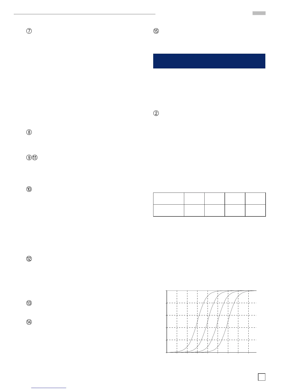
voltage at the component terminals
for the different ranges
0,5
1,E-01 1,E+00 1,E+01 1,E+02 1,E+03 1,E+04 1,E+05 1,E+06 1,E+07 1,E+08
Component impedance
Voltage (V)
Remarks: when measuring certain types of inductors it may
occurs that the HM8018-2 switches indefinitely between two
ranges. This due to the fact that generally the inductor value
depends of the current going through, the HM8018-2 will
gives different values from one range to an other because the
source resistance changes. This variation from one range to
another may be higher than the automatic mode hysteresis
that creates irresolution. So it is necessary to switch on
manual mode to fix the range.
Range
Change
|Z|
Range
Change
|Z|
1 to 2 |Z| > 15 Ω 2 to 1 |Z| < 13,5 Ω
2 to 3 |Z| > 330 Ω 3 to 2 |Z| < 300 Ω
3 to 4 |Z| > 3,3 kΩ 4 to 3 |Z| < 3 kΩ
4 to 5 |Z| > 33 kΩ 5 to 4 |Z| < 30 kΩ
5 to 6 |Z| > 330 kΩ 6 to 5 |Z| < 300 kΩ
Manual range
When an important quantity of similar components has to be
tested, the automatic mode process duration time can be avoided.
While a component is measured in automatic mode, press the
AUTO key. The range in use (selected by the instrument) is hold
and displayed a short time. It is possible to save the configuration
settings for a further use by pressing on the STORE key then
CONFIG key. If the impedance of the component is higher than
50 times the nominal value for the range (given by R source
resistance), the message « OFL » is displayed. Then you must
change the range. This not applies to the 15Ω range for which
overtaking is obtained for an approx. 18Ω impedance.
As far the higher range R6 allows measurements up to 99.9MΩ.
The manual range mode, thus, is to be reserved to precise
cases, and to avoid measurement instability and additional
uncertainty the instrument should be ever working in
automatic range mode.
Polarisation (Bias)
A DC bias voltage can be superposed to the test signal.
Electrolytic and tantalum capacitors need a positive bias voltage
for accurate measurement, although the HM8018-2 test voltage
is not high enough to damage the components. The internal 1V
DC bias voltage or an external bias voltage up to 100V allows to
perform measurements closer as possible to reality. The internal
bias voltage in addition allows performing measurements on
semiconductors junctions. To activate the bias voltage, press on
the BIAS key (10). The LED indicator just above, will lights up.
Pressing this key a second time disables the bias voltage.
However, make certain that the capacitor being tested is
connected with the correct polarity, DC voltage positive pole is
 Loading...


