EasyManua.ls Logo

Hammarlund HQ-140-X - User Manual

Hammarlund HQ-140-X
21 pages
Print Icon
To Next Page IconTo Next Page
Loading...
HQ-140-X
COMMUNICATIONS
RECEIVER
TECHNICAL DESCRIPTION &
OPERATING INSTRUCTIONS
460
West
34th
Street : : : :
New
York
1,
N.
Y.

Other manuals for Hammarlund HQ-140-X

Question and Answer IconNeed help?

Do you have a question about the Hammarlund HQ-140-X and is the answer not in the manual?

Summary

Errata and Corrections

Receiver Serial Number Specific Corrections

Lists specific changes based on receiver serial numbers for accuracy.

Schematic and Parts List Corrections

Details corrections for diagrams and parts list for specific receiver models.

Introduction to the HQ-140-X Receiver

Receiver Overview and Capabilities

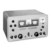
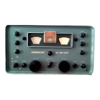
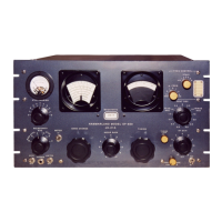
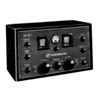
Introduces the HQ-140-X as a modern receiver with high performance and features.

Frequency Coverage and Selectivity

Details the tunable frequency range and the receiver's ability to separate signals.

Sensitivity and Noise Limiter

Explains the high sensitivity and the function of the noise limiter for clear reception.

Band Spread Tuning

Describes the band spread tuning feature for amateur bands and calibration.

Installation and Operation Guide

Initial Setup and Connections

Guides on unpacking, connecting speaker, and antenna for proper setup.

Basic Operation Controls

Explains the function of main tuning, volume, and other controls for operation.

Powering On and Tube Warm-up

Instructions on how to power on the receiver and check for tube warm-up.

Operating Controls and Settings

Initial Control Setup for Phone;CW

Recommended initial settings for controls like Tuning Range, AVC, Sensitivity for different modes.

Using the S Meter for Tuning

Guidance on using the "S" meter for accurate tuning and signal strength indication.

Beat Frequency Oscillator (BFO) and Limiter

Explains the use of BFO for CW and the Limiter for short wave reception.

Crystal Selectivity and Phasing

Describes how to use crystal selectivity for filtering and phasing to reduce interference.

Tuning Ranges and Procedure

Understanding Tuning Ranges

Lists the frequency bands and corresponding wave lengths covered by the receiver.

Tuning Procedure for Broadcast;Shortwave

Step-by-step guide for tuning broadcast and shortwave stations using main and band spread dials.

Design Overview of Receiver Stages

Pre-selection Stage

Explains the antenna input coupling and RF amplifier stage for signal selection.

Converter Stage Operation

Details the mixer and local oscillator function for frequency conversion.

Crystal Filter and Phasing Network

IF Amplifier Stages

Describes the three stages of IF amplification and their contribution to performance.

AVC System Function

Explains how the Automatic Volume Control minimizes signal strength variations.

S Meter Functionality

S Meter Operation and Purpose

Explains the "S" meter's role in tuning and indicating signal strength.

Meter Re-adjustment Procedure

Steps for re-adjusting the "S" meter pointer if necessary.

Second Detector and Noise Limiter

Noise Limiter Functionality

Details how the noise limiter reduces impulse noise for better intelligibility.

Beat Frequency Oscillator (BFO)

BFO for CW Reception

Explains the BFO's purpose for receiving CW signals and the CW TONE control.

Audio Amplifier Stage

Audio Output Stage

Describes the voltage amplifier and beam power amplifier for audio output.

Power Supply System

Power Supply Design

Explains the stabilized power supply, rectifier, and voltage regulation.

Antenna System

Antenna Suggestions and Matching

Provides recommendations for antenna types and matching for optimal reception.

Re-alignment Procedure

Equipment for Re-alignment

Lists the necessary equipment, including oscilloscope and signal generator.

IF Amplifier Re-alignment

Details the procedure for tuning IF transformers for symmetry and amplitude.

IF and RF Alignment Procedures

IF Alignment Steps

Step-by-step guide for aligning IF transformers using specific settings and adjustments.

RF Amplifier Alignment

Procedure for aligning RF and oscillator stages for dial calibration and tracking.

RF Alignment Procedure Continued

Tuning Dial and Trimmer Adjustment

Explains adjusting the tuning dial and trimmer capacitors for each band.

Antenna Terminal Alignment

Procedure for adjusting coils (L17, L12, L6) for maximum response at antenna terminals.

Maintenance and Troubleshooting

Common Trouble Sources

Identifies tube failure and component failure as primary sources of difficulty.

Voltage Checks and Troubleshooting

Discusses using voltage charts and schematics for locating defective components.

Parts List - Capacitors and Resistors

Capacitor Specifications

Lists capacitors with schematic designations and Hammarlund part numbers.

Resistor Specifications

Lists resistors with schematic designations and Hammarlund part numbers.

Parts List - Coils and Resistors

Coil Listings

Lists various antenna and H.F. oscillator coils with their respective part numbers.

Resistor Specifications

Lists resistors with schematic designations, wattage, and Hammarlund part numbers.

Parts List - Switches and Transformers

Switches and Assemblies

Details switches, transformers, and impedance assemblies with part numbers.

Component Specifications

Lists other components like crystals and transformers with part numbers.

Parts List - Continued (Resistors, Assemblies)

Resistor Specifications

Lists remaining resistors with schematic designations and Hammarlund part numbers.

Component Assemblies

Details various assemblies like Crystal Filter, IF, BFO with their part numbers.

Overview

The Hammarlund HQ-140-X is a modern, general-purpose, superheterodyne communications receiver designed for high performance and long-term stability. It features a self-contained, stabilized power supply operating from a 50-60 cps, 105-125 volt AC source.

Function Description:

The HQ-140-X is primarily designed for communications use, but also provides good fidelity for music and voice reproduction in standard and shortwave broadcast bands. It incorporates an unusually stable Beat Frequency Oscillator (BFO) for receiving telegraph or code signals. An "S" Meter provides accurate reports on received phone signals, and a Send-Receive switch with relay connections allows for associated transmitter operation without interference. The receiver's high sensitivity and superior Hammarlund noise limiter contribute to an inherently high signal-to-noise ratio, enabling reception of even weak stations. A patented Hammarlund crystal filter offers extreme selectivity for attenuating closely adjacent interfering signals. Automatic Volume Control (AVC) minimizes fading and signal strength variations, maintaining a comfortable and constant audio level. Either headphones or a loudspeaker can be used for audio output.

Important Technical Specifications:

  • Frequency Coverage: Continuously tunable from 540 Kc to 31 Mc (555 to 9.7 meters).
  • Intermediate Frequency (IF): 455 Kc (RTMA standard).
  • Power Supply: Self-contained, stabilized, operating from 50-60 cps, 105-125 volt AC.
  • Audio Output: At least 2 watts of undistorted output from a 6V6GT/G beam power amplifier (V9).
  • Output Transformer Impedance: 6 ohms, matching Hammarlund or other suitable permanent magnet speakers.
  • Antenna Input Impedance: Nominally 400 ohms.
  • "S" Meter Calibration: Factory adjusted so that approximately 50 microvolts input gives an S-9 reading. Each "S" unit indicates a 6 dB increase (doubling signal strength).
  • Tube Complement:
    • V1: 6C4 Triode (Oscillator)
    • V2: 6BA6 Remote Cutoff Pentode (RF Amplifier)
    • V3: 6BE6 Pentogrid Converter (Mixer)
    • V4: 6BA6 Remote Cutoff Pentode (1st IF Amplifier)
    • V5: 6BA6 Remote Cutoff Pentode (2nd IF Amplifier)
    • V6: 6BA6 Remote Cutoff Pentode (3rd IF Amplifier)
    • V7: 6AL5 Twin Diode (Detector, AVC; Noise Limiter)
    • V8: 12AU7 Twin Triode (1st AF Amplifier; BFO)
    • V9: 6V6GT/G Beam Power (Audio Power Output)
    • V10: 0C3/VR105 Voltage Regulator (Voltage Regulator)
    • V11: 5U4G Full Wave Rectifier (Rectifier)

Usage Features:

  • Controls: Large, comfortable, and carefully positioned controls for professional-type operation.
  • Tuning Ranges: Six continuous tuning ranges from 540 Kc to 31 Mc.
  • Band Spread Tuning: Available on the four higher frequency ranges, with direct calibration for 80, 40, 20, 15, and 10 meter amateur bands. An arbitrary 0-100 logging scale is also provided for other ranges.
  • Crystal Filter and Phasing Network: Six-position SELECTIVITY switch (including OFF) offers five increasingly selective bandwidths. Positions 1-3 for phone reception, 4-5 for sharpest CW/code reception. The PHASING control can attenuate interfering adjacent signals.
  • Noise Limiter: A series, self-adjusting noise limiter (one half of V7) reduces automobile ignition and other impulse noise without affecting intelligibility, and can be switched off if desired.
  • Beat Frequency Oscillator (BFO): Provides a wide choice of tones for CW code operation via the CW TONE control, with each calibration division representing approximately 1000 cycles. Operative only when the MAN-AVC-BFO switch is in the BFO position.
  • Antenna Compensator: An adjustable knob on the front panel allows resonating the receiver for optimum performance with the antenna in use.
  • Standby-Receive Switch: In STANDBY, the receiver is silent but ready for instant use.
  • Headphone Jack: Disconnects the speaker when headphones are plugged in.
  • Relay Jacks: Two pin jacks on the rear chassis for connecting to a transmitter's send-receive relay for break-in operation.

Maintenance Features:

  • Reliable Design: Designed for years of trouble-free service.
  • Common Failure Points: Tube failure is the most common issue, followed by component failure among small resistors and fixed capacitors.
  • Voltage Chart: A chart (Figure 11) provides voltages between tube socket terminals and chassis for troubleshooting.
  • Schematic Diagram: A detailed schematic diagram (Figure 7) aids in locating defective components.
  • Parts List: Includes values and Hammarlund part numbers for all components. Standard items can be purchased locally, while non-standard components are available from the factory.
  • Re-alignment Procedure: Detailed instructions for IF amplifier and RF amplifier re-alignment, requiring specialized equipment (cathode-ray oscilloscope, frequency modulated signal generator, output meter). Re-alignment is generally unnecessary for long periods due to the stability of iron-core permeability-tuned transformers and fixed silver-mica capacitors in the IF section, and factory alignment with standard crystals for RF and oscillator stages.
  • Professional Service: Due to the delicate nature of the receiver, it is recommended that service be entrusted to a qualified technician.

Hammarlund HQ-140-X Specifications

General IconGeneral
BrandHammarlund
ModelHQ-140-X
CategoryReceiver
LanguageEnglish

Related product manuals