Do you have a question about the Hammarlund SP-600-JX-17 and is the answer not in the manual?
Technical order number and former designation for the service manual.
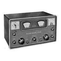
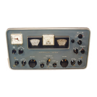
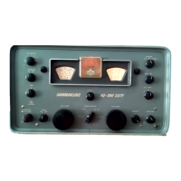
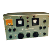
Identifies the specific radio receiver model and its manufacturer.
Indicates revisions and superseding pages for the manual.
Overview of the receiver's design, construction, and capabilities.
Outlines the intended use and operational scope of the receiver.
Lists key technical specifications and characteristics of the receiver.
Contains essential data points for the receiver's operation.
Specifies the frequency ranges covered by each of the receiver's bands.
Describes the audio output power and impedance matching.
Defines the receiver's sensitivity levels for different signal types.
Details the receiver's selectivity characteristics across different settings.
Presents audio and overall fidelity curves for the receiver.
Lists image and IF rejection ratios for various bands.
Explains all front and rear panel controls and their functions.
States no special test equipment is required for basic servicing.
Identifies specific tools needed for maintenance.
Details the construction of necessary cables.
Steps for unboxing and preparing the receiver for operation.
Guidance on connecting and setting up the receiver.
Describes the overall operational context and capabilities.
Details operation within space diversity receiving systems.
Explains how the receiver functions internally, referencing block diagrams.
Provides simplified explanations of the receiver's circuit theory.
Details the function of the second mixer tube.
Explains the operation and components of the 455-kc crystal filter.
Describes the function of the V9 and V10 intermediate frequency stages.
Details the audio frequency section of the receiver.
Explains the operation of the receiver's stabilized power supply.
Describes the mechanical design and its impact on performance.
Provides general information about receiver maintenance.
Outlines initial checks before detailed testing.
Details the performance tests to verify receiver operation.
Guides on identifying the location of receiver faults.
Describes the process for analyzing system faults.
Provides a step-by-step method for analyzing faults using test points.
Guidance on aligning and adjusting the receiver's circuits.
Outlines the schedule for inspecting receiver components.
Specifies the minimum performance benchmarks.
Method for analyzing system-level troubles.
General procedure for removing receiver subassemblies.
Steps for removing the frequency control unit.
Procedure for removing the mixer transformer T1.
Steps for removing the RF strip assembly.
Procedure for removing the four-gang tuning capacitor.
Steps for removing the front panel assembly.
Procedure for removing the main tuning dial.
Explains using diagrams for troubleshooting.
Provides charts for tube socket voltages and resistances for troubleshooting.
Illustrates the distribution of supply voltages.
Outlines procedures for aligning receiver circuits.
States receiver requires no lubrication during its life.
Defines the schedule for routine maintenance and inspections.
| Brand | Hammarlund |
|---|---|
| Model | SP-600-JX-17 |
| Category | Receiver |
| Language | English |