EasyManua.ls Logo

Hammond Organ A-100 Series User Manual

Hammond Organ A-100 Series
25 pages
To Next Page IconTo Next Page
Page #1 background imageLoading...
Page #1 background image
THEORY OF OPERATION
SERIES A-100
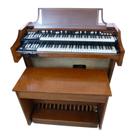
Figure 1
These Models of The Hammond Organ contain the entire tone-producing mechanism, which is
completely electrical in operation. Within it are produced all the tones and tone combinations of the
organ. The electrical waves are made audible by suitable amplifiers and loud speakers, contained
within the console. The block diagram (Figure 7) shows the chief components of the instrument.
Electrical impulses of various frequencies are produced within a unit known as the "tone generator",
containing a number of "phonic wheels" or "tone wheels" driven at predetermined speeds by a
synchronous motor and gear arrangement. Each phonic wheel is similar to a gear, with high and low
spots, or teeth, on its edge. As the wheel rotates these teeth pass near a permanent magnet, and the
resulting variations in the magnetic field induce a voltage in a coil wound on the magnet. This small
voltage, when suitably filtered, produces one note of the musical scale, its pitch or frequency depending
on the number of teeth passing the magnet each second.
A note of the organ, played on either manual or the pedal keyboard, generally consists of a fundamental
pitch and a number of harmonics, or multiples of the fundamental frequency. The fundamental and eight
harmonics available on each playing key are individually controllable by means of drawbars and preset
keys. By suitable adjustment of these controls the player is enabled to vary the tone colors at will.
The resulting signal passes through the expression or volume control and through the preamplifier
(where vibrato is introduced) to the power amplifier and the self-contained speakers.
Reverberation is added electrically by a second amplifier which drives a reverberation speaker, also
located in the console
1 tuttotastiere.com
Question and Answer IconNeed help?

Do you have a question about the Hammond Organ A-100 Series and is the answer not in the manual?

Hammond Organ A-100 Series Specifications

General IconGeneral
Tonewheel GeneratorYes
ManualsTwo
Drawbars9 per manual
Built-in EffectsVibrato/Chorus
AmplificationBuilt-in
SpeakerBuilt-in
PercussionSecond and Third Harmonic

Summary

Theory of Operation

Organ Tone Generation

Explains electrical tone generation via phonic wheels and signal processing.

Description

Starting the Organ

Details the procedure for turning on the organ using specific switches.

Preset Keys

Explains the function and operation of the preset keys for tone selection.

Harmonic Drawbars

Pedal Drawbars

Describes the drawbars used for the pedal keyboard and their function.

Volume Controls

Explains the normal/soft volume control and the swell pedal for volume adjustment.

Vibrato and Percussion

Vibrato Effect

Details the vibrato effect, its comparison to tremolo, and its mechanism.

Percussion Feature

Explains the "Touch-Response Percussion" feature and its controls.

Core Components

Tone Generator System

Describes the main tone generator, its frequencies, filters, and components.

Amplifier and Reverberation

Explains the power amplifier, reverberation amplifier, and the reverberation system's operation.

Tone Cabinets and Echo Control

Covers connecting external tone cabinets and the echo control feature.

Installation and Maintenance

Console Setup and Lubrication

Covers power connection, anchoring, generator lubrication, and lamp replacement.

Technical Section

Tone Generator Assembly

Introduces the electro-mechanical tone generator assembly and its mounting.

Starting and Synchronous Motors

Explains the function and operation of the starting and synchronous motors.

The Tone Wheels

Tone Wheel Mechanics and Lubrication

Details the tone wheel assemblies, construction, and lubrication requirements.

Generator Filters

Filters and Magnet Adjustment

Explains the function of generator filters and the magnet gap setting.

Manual Chassis Assembly

Manual Key Contacts and Busbars

Details the manual chassis, key contacts, and busbar connections for signal transmission.

Manual Contact Arrangement

Preset and Drawbar Interaction

Describes how keys, preset keys, and drawbars interact to control tone.

Manual Busbar Shifters

Shifter Function and Troubleshooting

Explains the busbar shifter for contact cleaning and troubleshooting noisy notes.

Manual Wiring

Preset Panel Connections

Explains how preset keys are wired to the preset panel for tone combinations.

Preset Key Mechanism

Details the mechanical operation and construction of preset keys.

Pedal Switch Assembly

Pedal Contact Arrangement

Details the pedal switch assembly, its contacts, and wiring to pedal drawbars.

Pedal Circuitry

Explains the pedal circuits, resistor panel, and filtering for pedal tones.

Pedal Keyboard Adjustments

Pedal Keyboard Tension

Explains pedal key tension adjustment.

The Hammond Vibrato

Vibrato Principle of Operation

Details the vibrato effect, phase shifting, and scanning mechanism.

Vibrato Line Box

Describes the vibrato line box and its filter sections.

Vibrato Switch and Scanner

Vibrato Switch

Shows the construction of the vibrato switch.

Vibrato Scanner

Explains the construction and operation of the vibrato scanner.

Percussion System

Percussion Tone Generation

Explains how percussion tones are produced by borrowing harmonic signals.

General Circuit Operation

Explains the general circuit operation for percussion tones.

Percussion Control Tablets

Control Functions Explained

Details the functions of various percussion control tablets and cutoff adjustments.

Accessories and Schematics

Earphones and Phono Input

Covers adding earphones and using the phono input jack.

Schematic References

Lists available schematics for the organ models.

Related product manuals