Preset Panel - Models A, AB, BC, BCV, BV, C, CV, D, DV, G. GV, RT
The tone signals from the preset keys on both manuals are carried by color-coded
wires to the preset panel in the back of the console.
The preset panel is a set of nine bars, wired to the taps on the matching
transformer, corresponding to different intensities of sound as shown by numbers
stamped on the bars. Each preset wire, carrying a single harmonic, is fastened under
a screw on the bar which represents the desired intensity of that harmonic. This is
equivalent to setting a harmonic drawbar to the corresponding number.
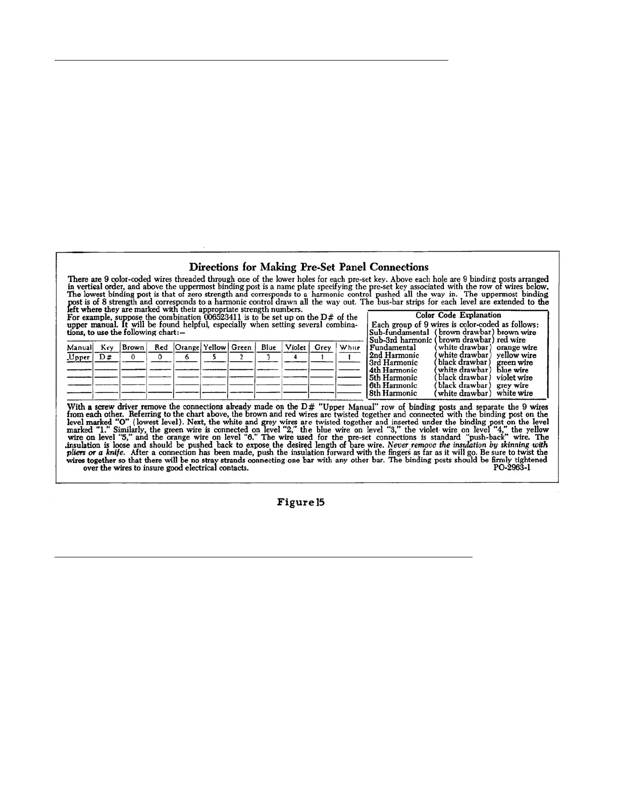
Preset combinations may be changed at will by removing the console back and
following the directions on a card inside. This card is reproduced below (figure
15).
Preset Panel - Models B-2, B-3, C-2, C-3, RT-2, RT-3, E, A-100, D-100
In these models the preset panel is divided into two sets of nine bars, each
connected to a separate matching transformer. One set is used for the swell (upper)
manual, and the other for the great (lower) manual and pedals. The preset panel on
Model E is slightly longer than on the other models to accommodate the two pedal
presets.
17