Do you have a question about the Hamworthy F100V and is the answer not in the manual?
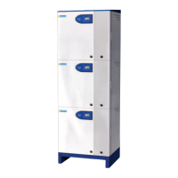
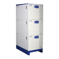
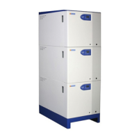
Lists the available boiler models and their output capacities.
Details additional control options like external sensors and sequence controllers.
Outlines warranty conditions and limitations for the boiler appliance.
Provides detailed dimensions and clearance requirements for installation.
Specifies considerations for choosing the boiler's installation location.
Details requirements and testing for the gas supply connection.
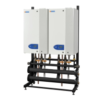
Covers general aspects of boiler assembly and handling.
Details how to connect water pipes, including safety valves and pump operation.
Explains the procedure for connecting the flue system to the boiler modules.
Checks required for the gas supply before commissioning.
Ensures correct ventilation and air supply to the plant room.
Verifies system flushing, pipework, valves, and pump operation.
Checks flue system design and clearance for proper operation.
Confirms correct and isolatable electrical connections and controls.
Procedures for checking the boiler's gas system for leaks.
Overview of the boiler's control system and connected peripherals.
Explains the meaning of symbols and labels on the boiler's fascia panel.
Details the layout and components of the boiler's user interface.
Provides a comprehensive view of all major boiler control components.
Lists and describes various parameters accessible via the info display.
Explains the logic behind the boiler's operation and display system.
Describes the meaning of symbols and segments on the boiler's display screen.
Shows the standard screen display and how it returns after inactivity.
How status and error codes are displayed on the screen.
Explains how lockout conditions are displayed and how to reset.
Steps for adjusting the heating circuit's temperature setpoint.
Details settings configurable by the end-user for personalized operation.
Details how the boiler protects against freezing conditions.
Explains the function to prevent bacteria growth in hot water.
Describes the pump's operation after heating or DHW cycles.
How the boiler protects itself from overheating.
Prevents excessive boiler cycling to improve efficiency.
Automatic adjustment of heating based on outside temperature.
Explains the safety temperature limiter and its function.
Describes the water flow switch and its role in preventing dry firing.
Details the function of the ignition controller and fault detection.
Procedure for replacing the HT electrode and flame probe.
Steps for replacing the flow and return water sensors.
Instructions for replacing the flue gas sensor.
How to replace the temperature limiter (limit stat).
Procedure for replacing the water flow switch.
Detailed steps for replacing the gas valve.
Guide for removing and replacing the boiler's fan unit.
Lists various spare parts with their corresponding part numbers.
Provides general gas data for different boiler models.
Specific gas connection and pressure data for each boiler module.
Electrical specifications for each boiler module.
Details mains power supply requirements and safety precautions.
Wiring diagrams for controlling multiple boiler modules externally.
Table of sensor resistance values at different temperatures.
Technical data related to flue connections and gas volumes.
General requirements and recommendations for flue system installation.
Guidelines for safe and efficient flue gas discharge.
Details how to manage condensate from the flue system.
Recommendations for adequate air supply for combustion and ventilation.
Requirements for natural ventilation in open flue installations.
Guidelines for mechanical ventilation systems.
Water data specifications for each boiler module.
Recommendations for water circulation system installation.
Information on the importance and selection of safety valves.
Requirement for an altitude gauge for monitoring water pressure.
Specifies minimum flow rates required for safe boiler operation.
Details controls related to water flow and the integral flow switch.
Instructions on configuring the boiler for cascade control.
| Max Heat Output | 100 kW |
|---|---|
| Output | 100kW |
| Modulation Range | 20-100% |
| Fuel Type | Natural Gas |
| Fuel | Natural Gas |