EasyManua.ls Logo

Hamworthy FLEET Series User Manual

Hamworthy FLEET Series
82 pages
To Next Page IconTo Next Page
Page #1 background imageLoading...
Page #1 background image
FLEET SERIES BOILERS
Wall Hung, Condensing , Room Sealed,
Fully Modulating, Pre-Mix,
Gas Fired Boilers for Heating & Domestic
Hot Water Installations
Installation, Commissioning
and Operating Instructions
Models: F40W, F50W, F60W, F70W, F85W, F100W,
F125W & F150W
NATURAL GAS I
2H
IMPORTANT NOTE
THESE INSTRUCTIONS MUST BE READ
AND UNDERSTOOD BEFORE INSTALLING,
COMMISSIONING, OPERATING OR
SERVICING EQUIPMENT
Question and Answer IconNeed help?

Do you have a question about the Hamworthy FLEET Series and is the answer not in the manual?

Hamworthy FLEET Series Specifications

General IconGeneral
ModelFLEET Series
Heat Exchanger MaterialStainless Steel
CategoryBoiler
InstallationFloor Standing
Boiler TypeCondensing Boiler
Modulation10:1
EmissionsLow NOx

Summary

Introduction to Hamworthy Fleet Series Boilers

Installation and Safety Requirements

Competent person installation requirements and adherence to safety regulations.

Gas Specification and Usage

Correct gas type and usage as per appendix reference.

Boiler Features and Models

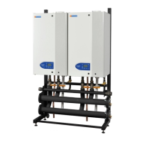
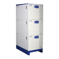
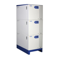
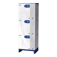
Description of the Fleet boiler's core features and model range.

System Connection Options

Connects to open or un-vented heating systems.

Boiler Model Range

List of available boiler models with their respective outputs.

Electrical Interface Capabilities

Compatibility with vfc and 0-10v analogue control signals.

Optional Accessories and Peripherals

Details on optional frame sets, water pipe kits, and controls peripherals.

Supply and Delivery of Hamworthy Boilers

Packaging and Handling Procedures

How boilers are packaged, delivered, and handled on site.

Warranty and Liability Information

Conditions for warranty coverage and liability limitations.

Size and Space Requirements for Installation

Plant Room Clearance and Access

Ensuring sufficient plant room space for installation and maintenance.

Frame Set and Pipe Work Kit Details

Site Location and Preparation Guidelines

Site Location Considerations

Requirements for wall or floor mounting and plant room environment.

Gas Supply Requirements

Specifications for gas piping, pressure, and testing.

Flue System Requirements

Flue Terminal Locations

Water Supply Requirements

Heat Exchanger Warranty Conditions

System Water Quality Standards

Condensate Connections

Electrical Supply Requirements

Boiler Assembly Procedures

General Assembly Procedures

Instructions for assembling boiler units and associated kits.

Water Connections and Safety Valve

Details on water connections and safety valve installation.

Flue System Connection Types

Types of flue systems compatible with the boilers.

Flue Installation Configuration Options

Electrical Connection Points

Pre-Commissioning Checks

Gas Supply Integrity Test

Ensuring gas supply is sound and purged before operation.

Ventilation Adequacy Check

Verifying correct ventilation and air supply to the plant room.

Pipework, Valves, and Pump Checks

Checking system pipework, valves, and pump for correct installation.

Flue System Checks

Electrical Connection Checks

Checks Prior to Lighting the Boiler

7.1 Boiler Gas System Leak Check

Procedure for checking gas system for leaks and integrity.

Water System Flushing and Preparation

Ensuring system is flushed and prepared before commissioning.

Pre-Lighting Checks

7.2.1 Boiler Component Checks

Verifying external controls, gas supply, system pressure, and flue ducts.

7.2.2 Gas Inlet Pressure Verification

Checking gas inlet pressure for constant and sufficient supply.

7.3 Commissioning Sequence Initiation

Steps to begin the boiler commissioning process.

7.3.1 Initial Boiler Lighting

Procedure for the first ignition of the boiler.

Ignition Controller Performance Check

Gas Supply Pressure Verification

Combustion Performance Checks

Gas Valve Adjustment Procedures

7.6.1 High Fire Throttle Adjustment

Adjusting gas valve throttle for high fire combustion.

7.6.2 High Fire Throttle Adjustment

Adjusting gas valve throttle for high fire combustion.

7.6.3 Low Fire Offset Adjustment

Adjusting gas valve offset for low fire combustion.

7.6.4 Low Fire Offset Adjustment

Adjusting gas valve offset for low fire combustion.

Setting Flow Rate for 20°C Delta T

Controls Operation Overview

8.2 System Control Configuration Overview

Diagram of boiler control system and peripherals.

8.2.1.1 Fascia Control Label Legend

Identification of labels on the boiler fascia.

8.2.1.2 Fascia Panel Overview

Overview of the boiler's fascia control panel layout.

Boiler Controls Component Diagram

Control Interface Navigation

8.2.1 Info Button Operation and Display Sequence

How to use the info button for display sequences.

Extended Info Mode and Parameter Levels

Accessing and navigating extended info mode levels.

Button Functions and Operations

Description of button functions and their operations.

Info Display Parameters and Descriptions

Control Operation and Display Philosophy

Control Screen Element Legend

Default and Status Code Display Modes

Lockout and Error Code Display

Adjusting Heating Circuit Setpoint Temperature

End User Parameter Settings

Chimney Sweep Function

Controller Stop Function

Heating Circuit Operating Modes

Error Code Display and Lockout

Boiler Functions and Features

8.3.1 Frost Protection Modes

Description of frost protection levels and activation.

8.3.2 Anti-Legionella Functionality

Ensuring domestic hot water is heated weekly to prevent bacteria.

8.3.3 Pump Overrun Operation

How the pump operates after heating mode or DHW period ends.

LMU Error Code Reference Table

BMS 0-10V DC Control Integration

LMU Fault Log Access and Interpretation

Operating Phases Diagram

Operating Phases Table

Fault Finding Procedures

9.1 Safety Temperature Limiter (Limit Thermostat)

Troubleshooting safety temperature limiter trips and resets.

9.2 Water Flow Switch Fault Diagnosis

Diagnosing issues related to the water flow switch.

9.3 Ignition Controller Fault Diagnosis

Troubleshooting faults related to the ignition controller.

Boiler Wiring Diagram

Servicing and Maintenance

10.1 Regular Servicing Recommendations

Guidance on recommended regular servicing schedules.

10.2 Annual Service Procedure

Step-by-step procedure for annual boiler service.

Replacement of Failed Components

11.1 HT Electrode and Flame Probe Replacement

Procedure for replacing HT electrode and flame probe.

11.2 Flow/Return Sensor Replacement

Steps for replacing flow and return sensors.

11.3 Flue Gas Sensor Replacement

Procedure for replacing the flue gas sensor.

Temperature Limiter Replacement

Water Flow Switch Replacement

Gas Valve Replacement

Fan Replacement

LMU Control PCB Replacement

Display Screen Replacement

Low Gas Pressure Switch Replacement

Air Pressure Switch Replacement

Recommended Spare Parts

APPENDIX B - Electrical Connections and Controls

B1.1 Electrical Supply Requirements

Guidelines for boiler electrical installation and supply.

External Control Wiring Diagram

BMS Connections and Control Options

Sensor Resistance Values Chart

APPENDIX C - Flue Data - Natural Gas

C1.0 Flue System Design Recommendations

Recommendations for designing flue systems for Fleet boilers.

Flue Materials and Suction Requirements

Flue Disconnection and Discharge

Surface Temperatures and Location

Condensate Discharge Requirements

Flue Equivalent Lengths Tables

Individual Flue Equivalent Lengths Tables

Twin Duct Flue Equivalent Lengths Tables

Important Note on B23 Flue Systems

Cascade Flue Equivalent Lengths

Flue Accessories

Concentric Flue Cuttable Extension Pieces

APPENDIX D - Ventilation

D1.1 Air Supply Requirements

Recommendations for air supply for combustion and ventilation.

Boiler House Temperatures

General Requirements for Air Supply

Mechanical Ventilation Flow Rates

APPENDIX E - Water Data

E1.1 Water Circulation System Design

Recommendations for designing the water circulation system.

Pressure Relief Valve Requirements

Altitude Gauge Requirement

Open Vent and Cold Feed Pipe Requirements

Minimum System Water Pressure Requirements

Integral Pump Performance Curves

APPENDIX F - Cascade Control and Mixing Circuit

Boiler Hydraulic Diagram Conversion for Cascade Control

Steps to convert hydraulic diagram for cascade control.

QAA73 Programmable Room Unit Integration

Useful User Information Section

Warranty Registration Card

Hamworthy Heating Accredited Agents

Hamworthy Heating Customer Service Centre

Related product manuals