Do you have a question about the Hamworthy F40V and is the answer not in the manual?
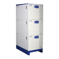
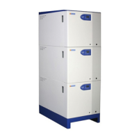
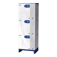
Details the specific models within the Fleet V series, including their power outputs.
Outlines the terms and conditions for warranty coverage and exclusions.
Guidelines for choosing an appropriate and safe location for boiler installation.
Requirements and safety checks for the natural gas supply connection.
Details on flue system design, installation, and materials for safe operation.
Requirements for water supply, treatment, and system connections.
Procedures for safely connecting and managing boiler condensate discharge.
Essential safety and connection guidelines for the boiler's electrical supply.
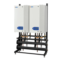
General instructions and precautions for assembling the boiler modules on site.
Guidance on connecting the flue system to the boiler modules for safe operation.
Checks required for the gas supply system before commissioning the boiler.
Verification of electrical connections and controls prior to boiler commissioning.
Procedure for performing a gas leak test on the boiler's system.
Steps involved in the initial lighting and commissioning of the boiler modules.
Explanation of symbols and indicators displayed on the boiler's control screen.
How to interpret lockout codes and their causes on the boiler's display.
Guide to adjusting user-configurable parameters for boiler operation.
Information on how error codes are displayed and what they signify.
Troubleshooting the safety temperature limiter and potential causes of overheating.
Diagnosing issues with the ignition controller and flame detection system.
Recommendations for routine annual servicing to ensure optimal boiler performance.
Detailed procedure for carrying out the annual service of the boiler.
Procedure for replacing the HT electrode and flame probe, noting fragility.
Instructions for replacing the gas valve on different boiler models.
Crucial safety and connection details for the boiler's electrical supply.
| Boiler Type | Condensing |
|---|---|
| Max Heat Output (kW) | 40 |
| Output | 40kW |
| Modulation | Yes |
| Max working pressure | 3 bar |
| Fuel Type | Natural Gas |
| Type | Wall mounted |
| Fuel | Natural Gas |