-10-
OPERATION MODEL 80
(FOR MODEL 125 SEE PAGE 14)
1. Check for proper assembly and adjustment and make sure that all bolts are tightened. Securely
retighten after a few hours of operation, as bolts can loosen up on new machinery. Check wheel bolts
upon delivery and periodically thereafter. Wheel bolts should be tightened at 60-65 ft./lbs. of torque.
2. Check the tires and inflate to the recommended pressure (6.70 x 15 tires to 35 pounds.)
3. Adjust the tractor hitch and attach the spreader to the tractor as described in the following sections.
4. Lubricate the machine completely and check the oil level of the gearbox.
5. Before operation run machine slowly to make sure that the spreader is operating and lubricated
properly.
TRACTOR HITCH
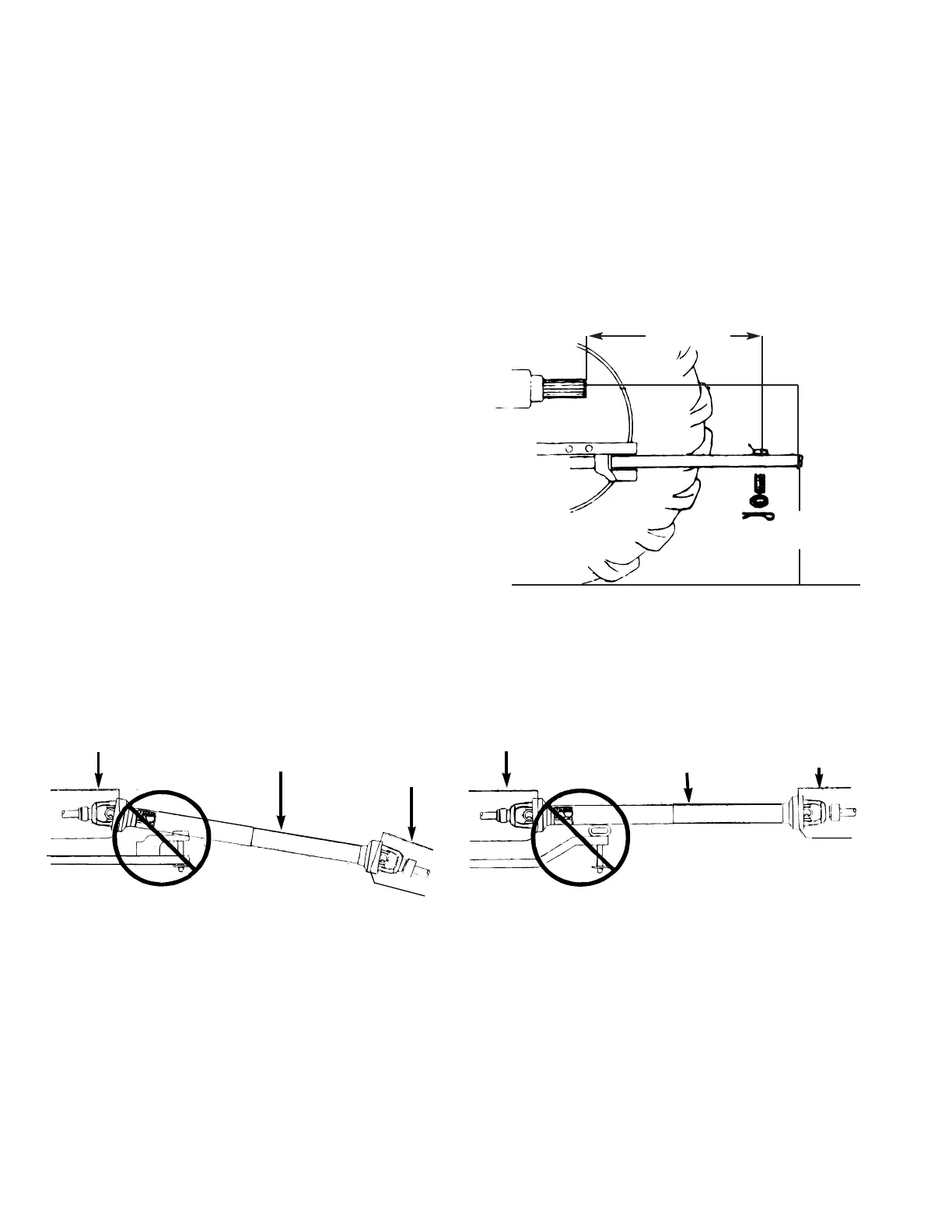
The hitch of the spreader is designed for a stan-
dardized tractor hitch. Adjust the drawbar so that it is
13 to 17 inches above the ground. Extend or short-
en it so that the horizontal distance from the end of
the tractor power take-off shaft to the center of the
hitch pin hole is 14 inches, as shown in drawing.
Use an adapter plate, if necessary, to secure the
proper distance. An improperly located hitch joint
may cause damage to the universal joints of the
power take-off. Secure the drawbar so that the hitch
pin hole is directly below the power drive line.
ATTACHING TO THE TRACTOR
1. Fasten the spreader hitch to the drawbar with a hitch pin that cannot bounce out. Use 3/4’’ to 7/8’’
diameter hitch pin to pull spreader.
2. Remove the weight from the jack (jack is not to be used when spreader is loaded). Swing jack forward
into its horizontal position, and lock it to provide a maximum ground clearance.
3. Slide spring loaded locking collar on PTO yoke rearward, and slide yoke onto the tractor PTO shaft.
Release spring loaded collar. Be sure pins fall into groove of tractor PTO shaft and collar snaps forward
into locking position.
CAUTION: Do not use a steel hammer to aid in joining PTO parts.
Be certain to disconnect all sources of power before servicing. Keep pant cuffs and other loose clothing away
from all chain and gear drives as well as the other moving parts. Keep off the equipment when in use, and
keep all safety shields in place; do not attempt to clean, grease or lubricate while the machine is running.
Never allow riders in or on the machine.
14’’ FOR 540 RPM
12’’
13’’ TO 17’’
FROM GROUND
HITCH
BOLT
WRONGWRONG
FIGURE 1
TRACTOR MASTER SHIELD
IMPLEMENT INPUT
DRIVELINE (IID)
IMPLEMENT INPUT
CONNECTION
SHIELD (IIC)
TRACTOR MASTER SHIELD
IMPLEMENT INPUT
DRIVELINE (IID)
IMPLEMENT INPUT
CONNECTION
SHIELD (IIC)
If this implement is attached to a tractor with a clevis
hitch (hammer-strap) style drawbar, the hammer-strap
must be removed to prevent damage to the IID guarding
and the IID telescoping members. [See Figure 1]
If this implement is attached to a tractor with an offset in
the drawbar, be certain it is in the down position to pre-
vent damage to the IID guarding and the IID telescoping
members. [See Figure 2]
FIGURE 2
 Loading...