DG3 Controller – Installation and Operation
Manual
540846-3 page 51 of 64 25/09/2015
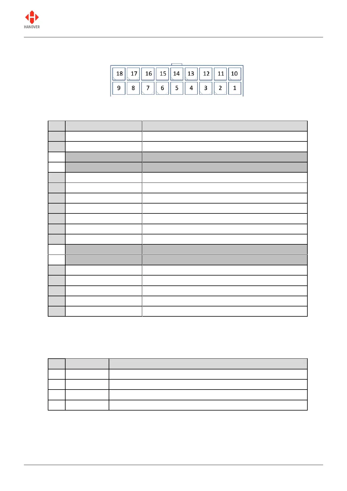
Appendix A: 18-way mini fit connector
Appendix A-1: 18-way mini fit connector: pinplan
RS485 B to display wiring (black)
Secondary comms (multifunction) routed to plug-in site
Secondary comms (multifunction) routed to plug-in site
Digital input 0 - isolated -ve connection
Secondary (slave) USB D+ (data signal +ve)
For use with secondary USB option only
RS485 channel A to display wiring (red)
Secondary comms (multifunction) routed to plug-in site
Secondary comms (multifunction) routed to plug-in site
Digital/power output can source up to 1.8A
Digital input 0 - isolated +ve connection
Secondary (slave) USB D- (data signal -ve)
Secondary (slave) USB power input (5v)
Appendix A-2: 18-way mini fit connector: wiring variation for pins 3, 4, 12 and 13
Variations according to the secondary communications protocol chosen are shown below:
DG3-01-1-0 RS-232 comms 7521-01-01 plug-in interface
RS-232 Plug-in Common Ground
RS-232 Plug-in Received Data
RS-232 Plug-in Transmitted Data