DG3 Controller – Installation and Operation
Manual
540846-3 page 52 of 64 25/09/2015
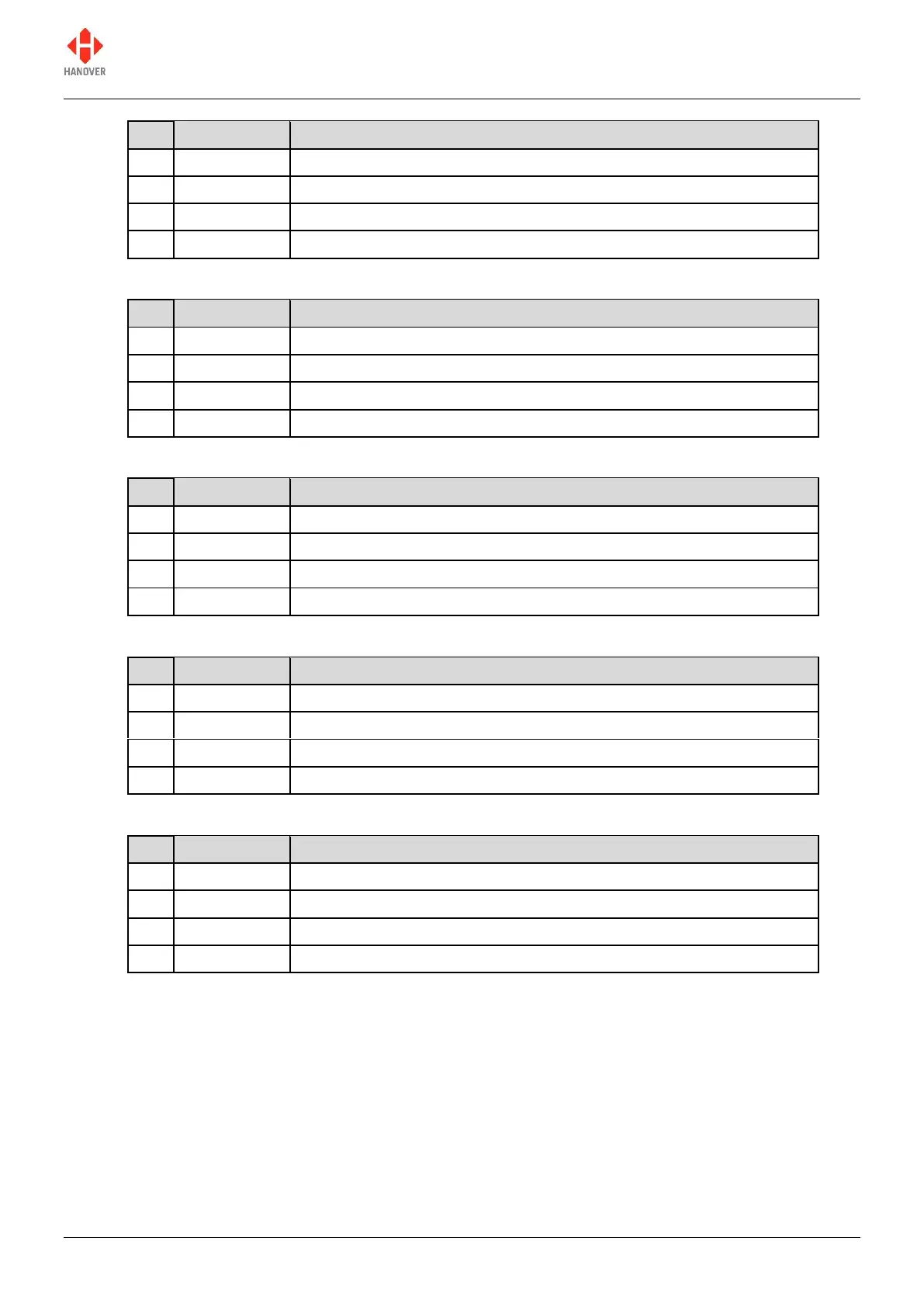
DG3-01-3-0 RS-422 comms 7202-01-07 plug-in interface
RS-422 Plug-in Received Data B
RS-422 Plug-in Transmitted Data B
RS-422 Plug-in Received Data A
RS-422 Plug-in Transmitted Data A
DG3-01-3-0 RS-485 comms 7202-01-07 plug-in interface
RS-485 Plug-in Transmitted + Received Data B
RS-485 Plug-in Transmitted + Received Data A
DG3-01-4-0 isolated RS-485 comms 7756-01-01 plug-in interface
Isolated RS-485 Plug-in Data B
Isolated RS-485 Plug-in Common Ground
Isolated RS-485 Plug-in Data A
Isolated RS-485 Plug-in 100Ω Termination to Common Ground
DG3-01-5-0 IBIS slave comms 7206-01-02 plug-in interface
WBMS (Wagenbus Masse senden) (Brown)
WBME (Wagenbus Masse empfangen) (Green)
WBSD (Wagenbus senden Data) (White)
WBED (Wagenbus empfangen Data) (Yellow)
DG3-01-6-0 SAE J1708 comms 7624-01-01 plug-in interface
 Loading...