EasyManua.ls Logo

Hansen HLM2 - User Manual

Hansen HLM2
20 pages
Print Icon
To Next Page IconTo Next Page
Loading...
Specifications, Applications,
Service Instructions & Parts
GAS DETECTION
SENSORS, MONITORS
& ALERT SYSTEMS
Bulletin A100b
JAN 2009
For Refrigerants and
other Common Gases
Standard Gas Sensor
Standard Gas Sensor
INTRODUCTION
Hansen Technologies offers a complete line of industrial
quality Gas Detection Sensors, Monitors and Alert
Systems for refrigerants and other common gases.
These state-of-the-art gas detection products utilize a
range of sensing technologies to suit a given application.
Available in several configurations to meet various
application requirements with optimum accuracy and
reliability.
APPLICATIONS
Hansen Gas Sensors are suitable for use in industrial
refrigeration engine rooms, cold storage rooms,
processing rooms, truck docks, and for relief valve vent
lines. They are also suitable for use in supermarkets,
and large institutional and commercial buildings.
Typical gas detection applications include Ammonia,
Carbon Dioxide (CO2), Hydrocarbons, HFCs, HCFCs
and CFCs.
ADVANTAGES
Hansen uses a wide variety of sensing technologies
including electrochemical, semiconductor and infrared
sensors to selectively detect most gases. These sensors
continuously determine the level of gas present in the
surrounding environment. The analog outputs (4-20mA
or 0-10V DC) can interface with nearly any existing
monitor, computer or PLC controller.
The sensing elements (except Basic and Extreme Gas
Sensors) are mounted externally on the enclosure. This
helps to provide quick response to potential leaks,
particularly in still air. Electronics are sealed in a NEMA4
enclosure (except Basic Gas Sensor) which protects them
from moisture, dust and the surrounding gases, which in
the case of ammonia can shorten the life of electronics.
The sensing elements are easily replaced.
Gas Sensors have built-in visual and audible alarms.
An auxiliary one amp SPDT relay output is standard.
Testing and recalibration procedures are simple.
KEY FEATURES–GAS SENSORS
Accurate, fast responding
Linear 4-20mA or 0-10V DC output
Audible alarm
Power indicator
SPDT alarm relay (Fail Safe Operation)
24V AC/DC low voltage power
Shipped factory calibrated and tested
CE approved
KEY FEATURES–MONITORS
Visual alarm
Audible alarm
Power indicator
Low level alarm relay
High level alarm relay
Fault relay (HLM6 only)
Economical
CE approved
KEY FEATURES−GAS ALERT SYSTEM
Provides local display and alarm based on
measured target gas level via gas sensor
Visual alarm, Amber LED light
Audible alarm (mutable)
Power indicator, Green
Numeric PPM reading
Bright LED Display
Shipped factory calibrated and tested
Question and Answer IconNeed help?

Do you have a question about the Hansen HLM2 and is the answer not in the manual?

Overview

The Hansen Gas Detection Sensors, Monitors & Alert Systems are a comprehensive line of industrial-quality gas detection products designed for refrigerants and other common gases. These systems utilize state-of-the-art sensing technologies to meet various application requirements with optimum accuracy and reliability.

Function Description

The Hansen Gas Detection systems continuously determine the level of gas present in the surrounding environment. They provide local displays and alarms, and can also interface with external monitoring systems.

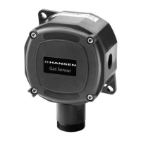
Gas Sensors: These units are designed to detect specific gases and output an analog signal (4-20mA or 0-10V DC) proportional to the gas concentration. They feature built-in visual and audible alarms, as well as an auxiliary one-amp SPDT relay output for fail-safe operation.

Monitors (HLM2, HLM6): These devices provide visual and audible alarms, power indicators, and alarm relay outputs. The HLM2 is a two-channel monitor with an internal audible alarm, while the HLM6 is a six-channel monitor with an external audible alarm and an additional fault relay output. They are designed to interface with gas sensors and provide centralized monitoring.

Gas Alert System: This system provides a local display and alarm based on the measured target gas level from a gas sensor. It features a visual amber LED light, a mutable audible alarm, a green power indicator, and a bright LED display showing numeric PPM readings. It can function as a standalone unit or as part of a larger monitoring system.

Important Technical Specifications

Gas Sensors:

  • Output: Linear 4-20mA or 0-10V DC.
  • Power: 24V AC/DC low voltage.
  • Alarm: Audible alarm, SPDT alarm relay (fail-safe operation).
  • Operating Temperature Range:
    • Basic/Standard: 0°F to 105°F (-17°C to 40°C).
    • Harsh/Vent Line/Explosion Proof: -40°F to 105°F (-40°C to 40°C).
    • Extreme: -60°F to 105°F (-51°C to 40°C).
  • Humidity Range (Non-Condensing): 0-95% (0-100% for Extreme).
  • Max. Loop Resistance: 1000 Ohms.
  • Enclosures:
    • Basic: NEMA1 (IP41) ABS.
    • Standard/Harsh/Vent Line: NEMA4 (IP65) ABS.
    • Extreme: NEMA4X (IP65) Stainless Steel.
    • Explosion Proof: NEMA7 Aluminum (Class I, Div II, Group C and D).
  • CE Approved.

Monitors (HLM2, HLM6):

  • Operating Temperature Range: 32°F (0°C) to 125°F (50°C).
  • Power Required: 120V AC (230V AC available).
  • Output:
    • HLM2: 2 SPDT dry contact relays (alarms) - 10 amp @ 230V AC.
    • HLM6: 2 SPDT dry contact relays (alarms) - 10 amp @ 230V AC, 1 SPDT dry contact relay (fault output) - 10 amp @ 230V AC.
  • Audible Alarm:
    • HLM2: Internal 80 dB.
    • HLM6: External 110 dB/12V DC.
  • CE Approved.

Gas Alert System:

  • Operating Temperature Range: -10°F (-23°C) to 125°F (50°C).
  • Humidity Range (Non-Condensing): 0-95%.
  • Voltage Requirements: 24V AC/DC, 50/60 Hz.
  • Display: LED, Red (numeric PPM reading, bright LED display).
  • Audible Alarm Sound Pressure: 97dB at 2 feet (mutable to 60dB).
  • Visual Alarm: Amber LED light (38 lumens).
  • Enclosure: Watertight, NEMA4X (IP65).

Usage Features

Gas Sensor Location:

  • Sensors should be located in accessible areas, away from moving equipment, thermal extremes, and strong drafts.
  • For heavy gases (vapor density > 1), sensors should be near ground level.
  • For light gases (e.g., ammonia), sensors should be mounted 12"-24" from the ceiling.
  • "Point" detection places sensors near likely leak sources, while "Perimeter" detection surrounds the area.
  • In ventilated rooms, sensors should be placed downstream of potential leak points.
  • For relief valve vent lines, the sensor element should be installed near the outlet of the vent line, with electronics mounted at a convenient height for servicing.

Wiring:

  • Gas Sensors: Use three-wire (VDC supply) or four-wire (VAC supply) twisted pair shielded cable. Signal wires (low voltage) should not be in common conduit with power wiring over 48 volts or near VFD equipment.
  • Monitors: Install on a wall or electrical panel. Connect specified AC power (120V or 230V) with minimum 18 gauge wire.
  • Gas Alert System: Can be mounted to any solid flat surface (screw or DIN-rail). Lower cover must be removed for wiring access.

Alarm Settings:

  • Gas Sensors: The trip point for the relay and alarm horn is set by adjustment screw A, with a default factory setting of 50% of the range. Time delays for alarms (1, 5, or 10 minutes) can be selected via jumpers JP5 and JP6. The alarm horn can be disabled via jumper JP2.
  • Monitors: Low level alarms reset automatically. High level alarms require a manual reset. The audible alarm can be disabled via a key switch.

Maintenance Features

Calibration:

  • Frequency: Recalibration should be performed at least once a year, or more frequently if exposed to high gas concentrations. Insurance companies and local agencies may require more frequent testing.
  • Procedure:
    1. Ensure system safety and power up for at least 24 hours for stabilization.
    2. Verify green LED is on and red LED is off. Disable internal horn (JP2 jumper).
    3. Zero Calibration: Adjust the zero potentiometer (Z) until the voltmeter reads between zero volts and +/- 0.090VDC in a target gas-free atmosphere.
    4. Span Calibration: Place the boot over the sensor element, apply calibration gas, and adjust the span potentiometer (S) until the output voltage reads between 4.95 to 5.00 volts DC.
    5. Do not re-adjust zero or span calibration until another 24 hours of powered operation.
  • Zero Offset (Electrochemical Sensors): A maximum zero offset of 2% may occur if calibrated at one temperature and moved to another. This can be adjusted if unacceptable.
  • Calibration Gas: Hansen provides NIST-traceable calibration gas cylinders for various refrigerants and PPM ranges. Store in a cool area (65°F/75°F).

Sensing Element Replacement:

  • Typical Life: Electrochemical (2-3 years), Semiconductor (7-8 years), Infrared (8-10 years). Exposure to high gas levels or extreme humidity can shorten life.
  • Basic Sensors: Three-pin (Ammonia) or six-pin (Halocarbon) plug-in element. Disconnect power, open enclosure, and lift element off the circuit board. Infrared elements (CO2) are not replaceable.
  • Standard, Harsh, Explosion Proof Sensors: Externally mounted. Disconnect power, open enclosure, disconnect cable, and unscrew element from enclosure.
  • Extreme Sensors: Internally mounted. Disconnect power, remove nut and gasket, open enclosure, and disconnect cable.
  • After replacement, connect power, allow 24 hours for stabilization, recalibrate, and install the cover.

Troubleshooting:

  • No lights on monitor: Check power, circuit breaker/fuse, or unit warming up.
  • Red light on, no alarm: Check horn deactivation, wiring/sensor fault, calibration, or missing resistor in unused sensor channel (HLM6).
  • Sensor green light off: Check wiring, power supply, HLM6 fuse, or sensor damage.
  • Sensor output 0.5mA (4-20mA) or 0V/.5V (voltage output): Sensing element disconnected or failed. Check wiring and installation.

Hansen HLM2 Specifications

General IconGeneral
BrandHansen
ModelHLM2
CategoryAccessories
LanguageEnglish