5
A100b
JAN 2009
*ADD 3.25” (83) FOR SHIELD
WIRING GAS SENSORS
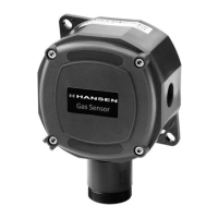
Install the Hansen Gas Sensor in an area where operating
personnel can easily monitor the remote sensor. Refer
to Gas Sensor Location on page 3 for suggestions on
proper placement of Remote Sensors.
Use three-wire (VDC supply voltage), twisted pair
shielded cable such as Belden 8770 or equivalent to
connect the gas sensor to the gas monitor (page 13),
GAS Alert System (page 17), customer supplied PLC or
computer (page 18). When powering the gas sensor
from a VAC power supply use four-wire, twisted pair
shielded cable, such as Belden 82418 or equivalent.
Connect the power input wires to terminals ØV and +V.
Set applied voltage jumper to appropriate AC or DC
position. Extreme Gas Sensor requires an additional
external 24V AC or DC power supply wired with 18 AWG
cable. Refer to Fig. K for wiring details. Connect the
signal wire to terminal I for 4-20mA output or V terminal
for 1-5 volt output. The 4-20mA output is best for long
distances to the monitor and where electrical noise is
a problem. The voltage output is for short distances
within 10 feet (3 m) of the monitor. The maximum 4-20mA
cable length is 1000 ft (300 m).
Under no circumstances should the gas sensor low
voltage signal wires be in a common conduit, tray or
wiring panel with power wiring over 48 volts. Do not run
wires near variable frequency drive (VFD) equipment.
When using the gas sensors connected directly to a
customer supplied PLC or computer, refer to Fig. J for
wiring details.
Hansen recommends backup of gas detection system
with an uninterruptable power supply to provide battery
backup in the event of power failure.
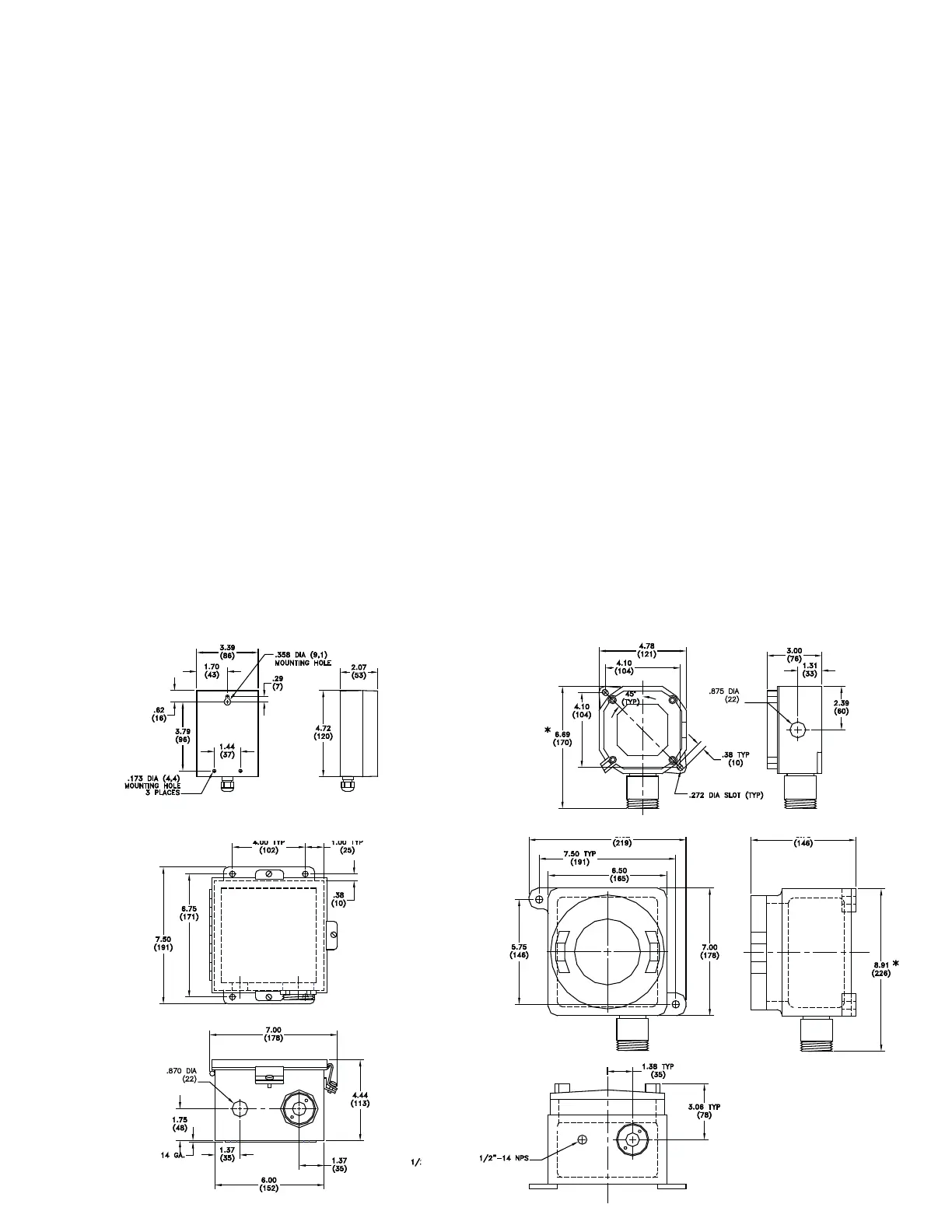
INSTALLATION
Mounting the gas sensor varies by model. Refer
to Installation Dimensions below for mounting
requirements.
SENSING ELEMENT
Typical sensor life is based on normal operating
conditions. Exposure to high levels of the target gas
will shorten these times. The typical sensor life of the
electrochemical gas sensor element is 2-3 years; typical
sensor life for semiconductor element is 7-8 years; and
typical sensor life for infrared element is 8-10 years.
Recalibration should be performed at least once a year.
Calibration can be performed locally at sensor installation
site. If desired results cannot be achieved or if signal
reads 0.5mA, replacement of the sensor element may be
required. See Sensor Element Replacement section
for further instruction.
Note: Insurance companies, local and state agencies
may require more frequent testing and calibration; refer
to insurance carrier mandates as well as local and state
codes.
INSTALLATION DIMENSIONS
INCHES (MM)
BASIC STANDARD & HARSH
EXTREME EXPLOSION PROOF
 Loading...