4
A100b
JAN 2009
GAS DETECTION SYSTEM CONFIGURATIONS
There are a number of typical installation configurations to meet national and local codes.
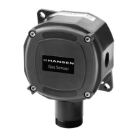
RELIEF VALVE VENT LINE
Often the vent line is extended high above the ground or roof. The sensor element can be installed near the outlet of
the vent line and the gas sensor electronics mounted at a convenient height for servicing. A small length of tubing
can be run for injecting test gas near the sensor element. Install a plug with a small opening to allow a small air flow
to clear fugitive gases and detected gas after a release. Hansen recommends the alarm setting at 5000 PPM.
For water diffuser systems where the relief valve vent piping is diverted into a water diffusion tank, install the vent
line sensor on the diffusion tank exhaust vent, not on the piping to the diffusion tank.
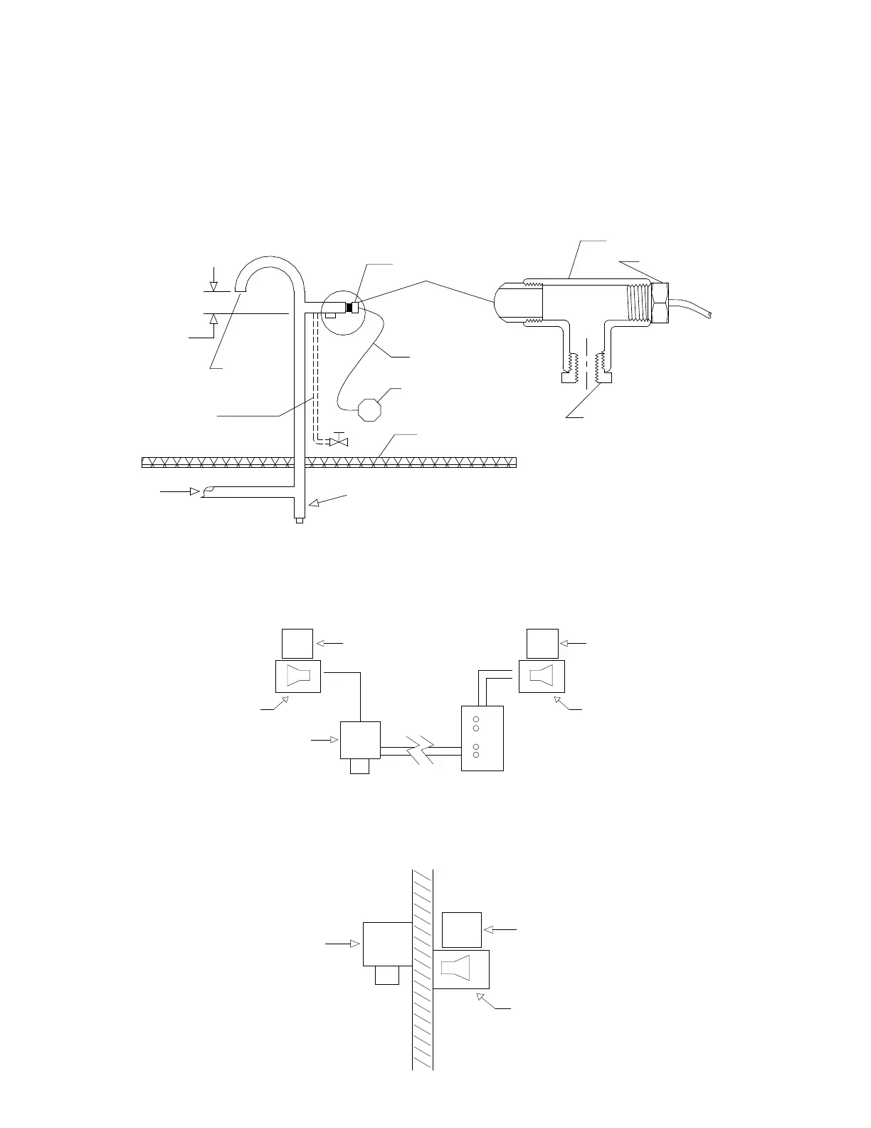
LOCAL AND REMOTE VISUAL/AUDIBLE ALARM
Sometimes it may be advantageous to have both local and remote displays and alarms. A display/alarm control
inside or just outside of a room can be monitored and the same display/alarm or a Hansen monitor in the control
room can also alert the operator to an abnormal condition in the plant.
STAND ALONE CONTROL
The Hansen Gas Sensor can operate as a stand alone device. All that is needed is a 24V AC/DC power supply for
the gas sensor and auxiliary devices for light, horn or digital readout, such as the Hansen GAS Alert System.
INDOOR OUTDOOR
VISUAL
AUDIBLE
GAS
SENSOR
VISUAL
UDIBLE
LARM ALARM
ALARM
ALARM
INDOOR OUTDOOR
VISUAL ALARM
AUDIBLE ALARM
GAS
SENSOR
INSIDE SPACE OUTSIDE SPACE
GAS SENSOR ELEMENT
10' (3m) CABLE, MAX
WEATHER PROOF
GAS SENSOR ELECTRONICS
RELIEF LINE DISCHARGE HEADER
DRIP LEG
INSTALL
GAS SENSOR
ELEMENT WITHIN
2' (.7m) OF
DISCHARGE
VENT LINE APPLICATION
PROTECT
EXIT WITH
SUITABLE
OPTIONAL TUBING
LINE For "BUMP" TESTING
GAS AND AIR PURGE
ROOF LINE
PIPE TEE
GAS SENSOR ELEMENT
1" X 3/4"
TO ALLOW A SMALL AMOUNT OF
AIR FLOW TO CLEAR DETECTED
GASES AND AVOID FALSE ALARMS
REDUCING BUSHING
SCREEN
 Loading...