3
A100b
JAN 2009
GAS SENSOR SPECIFICATIONS
BASIC STANDARD HARSH VENT LINE
EXPLOSION
PROOF
EXTREME
OPERATING TEMPERATURE
RANGE
0ºF TO 105ºF
(-17ºC TO 40ºC)
0ºF TO 105ºF
(-17ºC TO 40ºC)
-40ºF TO 105ºF
(-40ºC TO 40ºC)
-40ºF TO 105ºF
(-40ºC TO 40ºC)
-40ºF TO 105ºF
(-40ºC TO 40ºC)
-60ºF TO 105ºF
(-51ºC TO 40ºC)
OPERATING CURRENT @ 24V DC
230mA/6W 50mA/1W 280mA/7W 280mA/7W 280mA/7W 1900mA/46W
OPERATING CURRENT @ 24V AC
460mA/11VA 100mA/2VA 560mA/13VA 560mA/13VA 560mA/13VA 2100mA/50VA
VOLTAGE REQUIREMENTS
12-24V AC/DC* 24V AC/DC*
HUMIDITY RANGE
(NON-CONDENSING)
0-95% 0-100%
MAX. LOOP RESISTANCE
1000 OHMS
OUTPUT
4-20mA, 0-5V, 1-5V, 0-10V, 2-10V DC
4-20mA SIGNAL OUTPUT
Isolated, 2 wire
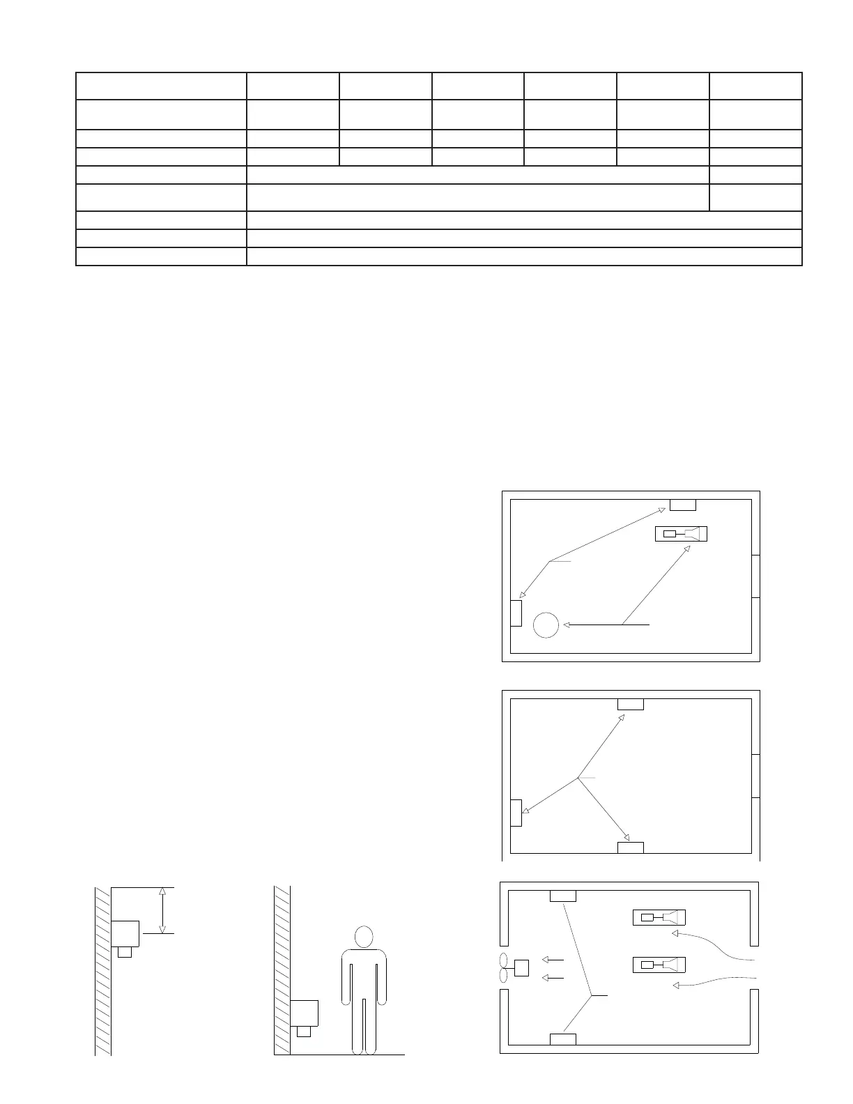
PLACE SENSOR
NEAR OPERATING
EQUIPMENT
OPERATING
EQUIPMENT
PLACE SENSORS
AROUND PERIMETER
OF LARGE ROOM
AIR FLOW
PLACE SENSOR(S)
BETWEEN EQUIPMENT
AND EXHAUST FAN
12" - 24" FROM CEILING
LIGHT GASES (AMMONIA)
HEAVY GASES (CO2, HALOCARBON)
MOUNT NEAR GROUND LEVEL
GAS SENSOR LOCATION
Sensors should be located in an accessible area
for maintenance and testing, but away from moving
equipment that could accidentally come in contact with
the sensor. Avoid thermal extremes (close to heaters)
and do not place unprotected in direct, strong drafts/
airflows, near exit doors, or areas where falling water or
condensing moisture are present. If high humidity is
always present, power up the unit as soon as possible,
as long term exposure can shorten the life of the gas
sensing element. Select the unit for harsh environments
where a condensing atmosphere may be present. In
blast freezers, mount the gas sensor below the coil to
avoid high moisture and steam during defrost.
The two generally accepted methods of locating sensors
are “Point” and “Perimeter” detection. “Point” detection
is where sensors are located near the most likely sources
of leakage. “Perimeter” detection is where sensors
completely surround the area in question. The size and
nature of the area will help to decide which method is
the most appropriate. Air flow should be considered
in a ventilated room. Place sensors downstream of
potential leak points.
Any sensor which is to be used for detecting a gas
with a vapor density greater that one (i.e. heavier
than air) should generally be located nearer ground
level. Conversely, for any lighter than air gases such
as ammonia, the sensor needs to be located higher up.
Typically ammonia sensors are mounted 12˝ - 24˝ (.3 to
POINT DETECTION
PERIMETER DETECTION
VENTILATED ROOM
MOUNTING HEIGHT OF SENSORS
.5m) from the ceiling. Sensors should not be located
too close to the ceiling as hot air trapped under the
ceiling may act to buffer the target gases from reaching
the sensor.
The number of sensors in each area is a function of local
codes and regulations and the customers’ guidelines
for gas detection.
*AC or DC user selectable. See pages 6 and 7 for configuration.
 Loading...