Page 7
;&(%$*4.8"4,7%<'*#$"&8#=%/7*,#*%4,77%>?@@@?@AA?BCDC1
ITEM 63584
GH;6EIJK6LHEMJNOHMNE6NHNF6 G6EPK
G*$%P/
L*,9%$.*%6NEML6%MOKJLEHNE%GH;6EI%MN;JLOHEMJN%#*4$"&8%,$%$.*%+*3"88"83%&2%$."#%5,8',7%
"847'9"83%,77%$*e$%'89*(%#'+.*,9"83#%$.*(*"8%+*2&(*%#*$%'/%&(%'#*%&2%$."#%/(&9'4$1
EJ%KL6!6NE%G6LMJPG%MN`PLI%HNU%;ML6-%%J/*(,$*%&87V%)"$.%/(&/*(%#/,(d%,((*#$&(%"8#$,77*91
J/*(,$"&8%&2%$."#%*<'"/5*8$%5,V%4(*,$*%#/,(d#%$.,$%4,8%#$,($%2"(*#%,(&'89%9(V%]*3*$,$"&81%
H%#/,(d%,((*#$&(%5,V%+*%(*<'"(*91%
E.*%&/*(,$&(%#.&'79%4&8$,4$%7&4,7%2"(*%,3*84"*#%2&(%7,)#%&(%(*3'7,$"&8#%(*7,$"83%$&%2"(*%
/(*]*8$"&8%(*<'"(*5*8$#1
At high altitudes, the engine’s carburetor, governor, and any other parts that control the fuel-air ratio
will need to be adjusted by a qualified mechanic to allow efficient high-altitude use and
to prevent damage to the engine and any other devices used with this product.
R(&'89"83
1. The Generator must be properly grounded
in accordance with all relevant electrical
codes and standards before operation.
Have the unit grounded by a qualified electrician
if you are not qualified to do so.
2. To ground the Generator, connect a #4 AWG
grounding wire (not included) from the Grounding
Terminal on the Control Panel to a grounding rod
(not included). The grounding rod must be an
earth-driven copper or brass rod (electrode)
which can adequately ground the Generator.
3. Refer to local regulations for
ground source information.
67*4$("4%G$,($*(%S,$$*(V%F&88*4$"&8
For the electric start function, the included 12 VDC
Battery must be connected before first use.
1. Remove the Battery Access Door.
2. Make sure the black strap stretches over the top of
the Battery and hooks into the Battery Platform.
3. Remove the covers from the Battery Terminals.
4. Locate the black and red battery cables.
5. Connect the red cable to the positive battery
terminal first. Then connect the black
cable to the negative battery terminal.
6. Replace the Battery Access Door.
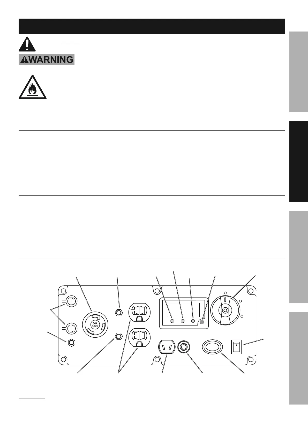
F&5/&8*8$#%,89%F&8$(&7#
RESET
AC 120V
AC 120V
RESET
PARALLEL
OUTLETS
DC 12V
8A MAX
RESET
ESC THROTTLE STARTER
OFF
OFFON
RUN
START
GROUND
F&5+"8,$"&8%
G)"$4.%
T&)%J"7
J]*(7&,9
J'$/'$
R(&'89%
E*(5"8,7
120 VAC 20 A
L*4*/$,47*#
120 VAC 30 A%
L*4*/$,47*
12 VDC
L*4*/$,47*
12 VDC Breaker
L*#*$%S'$$&8
K,(,77*7%\"$%
E*(5"8,7#
64&8&5V%
^6GF_%G)"$4.
120 VAC Breaker
L*#*$%S'$$&8
120 VAC Breaker
L*#*$%S'$$&8
U"#/7,V%F&8$(&7%
S'$$&8
683"8*%
G)"$4.%
;"3'(*%H-%%F&8$(&7%K,8*7
QHLNMNRX%%;&77&)%K,(,77*7%\"$%"8#$('4$"&8#%2&(%4&88*4$"&8%,89%'#*%&2%,%
K,(,77*7%\"$%^K,(,77*7%\"$%,89%"8#$('4$"&8#%#&79%#*/,(,$*7V_1
 Loading...