IFU-10891[C] HemaPRO User Manual
Page 9 of 33
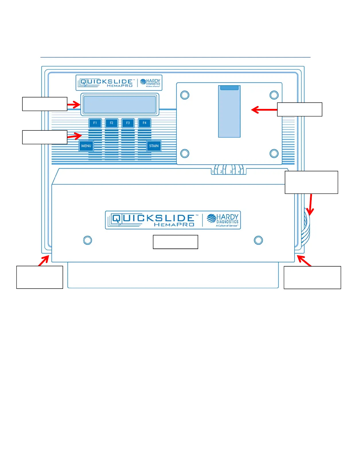
7.0 InstrumentDiagram
The basic anatomy of the HemaPRO is identified in the diagram above.
Please use this diagram to familiarize yourself with the common areas of the HemaPRO unit.
Display – User interface where options are presented.
Keypad – Contains F1, F2, F3, F4, Menu, and Stain.
Cuvette – Houses the slide during the staining process.
Power Cord Input – The power cord plugs into the left side of the machine.
Pump Cover – Covers the reagent supply and waste drain pump rollers and tubing.
Reagent and Waste Line(s) – These lines wrap around the left side to the back of the unit. The
HemaPRO Reagent Kit sits behind the instrument on the designated platform.
Stain Activation Module Input – The Stain Activation Module (included with the QuickSlide™
HemaPRO Reagent Kit) plugs into the right side of the unit.
Pump Cover
Stain Activation
Module Input
Power Cord
Input
Reagent and
Waste line(s)
Keypad
Display
Cuvette
 Loading...