Do you have a question about the Hardy Process Solutions HI 6500 Series and is the answer not in the manual?
Provides contact information for international field service.
Provides an overview of the manual and contact info for support.
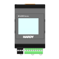
Describes the features and capabilities of the HI 6500 series instrument.
Lists common industrial weighing applications for the HI 6500 series.
Details the key features and functionalities of the HI 6500 series.
Explains the suite of productivity tools offered by Hardy Process Solutions.
Describes electronic calibration methods that do not require test weights.
Explains the system diagnostics program for troubleshooting.
Guides users through the initial setup process of the HI 6500 instrument.
Lists fundamental technical specifications for the HI 6500 series.
Covers general specifications like number of channels and update rate.
Explains the function of WAVERSAVER for filtering vibration and noise.
Details the advanced WAVERSAVER+ features for enhanced stability.
Describes tests for diagnosing unstable weight readings using IT.
Details the input capabilities and load cell connections.
Lists supported network communication protocols.
Specifies operating and storage temperature, and humidity ranges.
Lists the certifications and approvals obtained by the instrument.
Describes available enclosure options for mounting.
Provides instructions for unpacking the instrument and checking contents.
Lists common spare parts with their references and quantities.
Lists the tools required for installation.
General guidance for installing the HI 6500 series instrument.
Details the four mounting configurations available for the instrument.
Instructions on how to mount the optional front panel display.
Guides on how to create custom length display interface cables.
Instructions for mounting the instrument on a DIN rail.
Detailed steps for Panel Mount Option 1 installation.
Detailed steps for Panel Mount Option 2 installation.
Step-by-step guide for wall mounting the instrument.
Instructions for mounting the display in a remote location.
Covers the connection and requirements for DC power input.
Illustrates wiring diagrams for standard and C2 load cells.
Details how to connect the instrument to junction boxes and summing cards.
Instructions for configuring Ethernet TCP/IP settings.
Steps for connecting the instrument to a Local Area Network.
How to configure DHCP settings via the front panel.
Steps to configure a fixed IP address via the front panel.
Details on connecting the instrument directly to a PC via Ethernet.
Steps for configuring PC network settings (Windows 2000, XP, 7).
Information on using Ethernet UDP for instrument communication.
Describes I/O tables for communication protocols like EtherNet/IP, Modbus, Profibus.
Details on configuring Modbus TCP communication.
Instructions for configuring Modbus-RTU communication via RS-485.
Configuration and commands for Profibus-DP communication.
Steps to configure Profibus via the web interface.
Configuration for serial printing using RS-232.
How to use a USB memory stick for saving and restoring parameters.
How to set instrument parameters using the web interface home page.
Navigating front panel menus to configure instrument settings.
Explains the function of each button in the command cluster.
Guide to entering numeric and alphanumeric data via the interface.
Overview of parameter categories and their grouping.
Details the options within the Calibration Menu.
Specific commands and parameters for C2/eCAL calibration.
Sets tolerance for motion during calibration.
Instructions for executing the C2 eCAL calibration process.
Details on performing multi-point calibration.
Explains gravity correction for calibration.
Sets the reference weight for calibration.
Configures load cell sensitivity settings.
Commands and parameters for traditional hardware calibration.
Sets the low weight value for hard calibration.
Sets the high weight value for hard calibration.
Lists parameters for setting up instrument communication.
Configuration for Ethernet TCP/IP communication.
Configuration for Modbus-RTU communication.
Configuration and commands for Profibus-DP communication.
Settings for serial printer communication via RS-232.
Managing parameters using a USB memory stick.
Configuration for analog 4-20mA output (HI 6510 only).
Accesses diagnostic tests and parameters.
Configures display-related parameters.
Adjusts the display panel brightness level.
Configures power saving features for the display.
Configures the split screen display mode for multiple instruments.
Assigns a unique identifier to the HI 6500 series instrument.
Accesses filter parameters like NumAverages and WAVERSAVER.
Sets the number of weight readings for averaging.
Configures WAVERSAVER settings for noise filtering.
Advanced filtering parameters for XP models.
Configures instrument operations like Tare, Zero, Auto Mode, and Count.
Settings related to Tare operations.
Allows users to avoid pushing Tare button for containers.
Settings related to Zero operations.
Enables automatic switching for Zero and Tare operations.
Configuration for counting pieces.
How to determine piece count based on known or unknown unit weight.
Steps to perform before calibration, including load cell checks.
Verifies electrical connections and load cell signals.
Measures load cell output signals for troubleshooting.
Verifies that weight readings change correctly when a load is applied.
Describes electronic calibration without test weights.
Compensates for gravity variations based on location.
Instructions for performing C2/eCAL calibration via the web interface.
Instructions for performing C2 calibration using the front panel.
Calibration method using physical test weights.
Steps for performing hard calibration via the web interface.
Steps for performing hard calibration using the front panel.
Performing calibration at multiple points for better accuracy.
Prerequisites and initial checks before operating the instrument.
How to switch between Gross, Net, and Count weighing modes.
Procedures for zeroing the scale.
Procedures for taring the scale.
Behavior when Auto Mode Tracking is enabled.
Configures and uses the instrument in count mode.
How to determine piece count based on known or unknown unit weight.
Web-based page for monitoring readings and performing Zero/Tare.
Information on using the split screen mode for multiple instruments.
Wiring instructions for connecting units to a display panel.
Guides on how to create custom length display interface cables.
Options for securing the display and controlling access.
Details the security setting that blanks the screen and disables buttons.
Explains the security setting that disables the front panel keypad.
Security setting that disables the configuration button and prevents parameter modification.
Additional security levels limiting access to sensitive parameters.
How to view or modify security parameters and passwords.
How calibration security locks restrict access to calibration parameters.
How read-only parameters are protected and modified.
Important notes and cautions for disassembly and reassembly.
Lists and explains common error messages and their causes.
Using the IT software utility for troubleshooting.
Performs a comprehensive stability test on the weighing system.
Computes A/D count variations to indicate pass or fail status.
Analyzes weight changes with WAVERSAVER filtering.
Tests overall system performance and signal voltage readings.
Checks if the scale returns to a zero reading when empty.
Identifies individual load cell problems using the IT summing junction box.
An index of troubleshooting flow charts.
Guidelines for reviewing electrical and mechanical factors affecting stability.
General guidelines for addressing electrical, mechanical, or configuration problems.
Checks for proper electrical installation to ensure system stability.
Verifies correct mechanical installation for proper system function.
Adjusts configuration and filter settings to improve weight reading stability.
Overview of IT and Stability tests for diagnosing system health.
Tests the scale's ability to return to zero after weight changes.
Checks individual load sensor millivolt output.
Addresses errors encountered during the calibration process.
Specific checks for correct mechanical installation.
Detailed checks for electrical installation and grounding.
Points to check for proper installation and wiring.
Troubleshooting steps for a blank or locked front display.
Troubleshooting for the analog 4-20mA output on the HI 6510.
Overview of available tests and diagnostic features.
How to perform diagnostic tests using the front panel.
Accessing and copying instrument parameters.
Overview of typical system and load cell testing.
Details on using the IT diagnostics utility for load cells.
Describes the stability test for checking A/D counts.
Tests system performance and signal voltage readings.
Running IT tests via communications.
Describes mounting options for swivel enclosures (table, wall, pedestal).
Instructions for installing cable glands and vents.
Guidelines for installing wiring through glands.
Steps for assembling the unit with the swivel mount enclosure.
| Brand | Hardy Process Solutions |
|---|---|
| Model | HI 6500 Series |
| Category | Computer Hardware |
| Language | English |