TM
9-879
90
MOTORCYCLE, SOLO
(HARLEY- DAVIDSON MODEL
WLA]
Section XIX
GENERATING SYSTEM
Poiagraph
Description
90
Clean
commutator ,
91
Armature bearing
special lubrication
92
Remove generator 93
Install generator
94
Cut-out relay
~
95
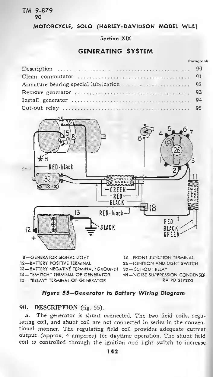
8
—
GENERATOR SIGNAL
LIGHT
12— BATTERY POSITIVE TERMINAL
13— BATTERY
NEGATIVE
TERMINAL
IGROUND)
14—
-SWITCH" TERMINAL OF
GENERATOR
15—
"RELAY"
TERMINAL OF
GENERATOR
18-
FRONT JUNCTION TERMINAL
26—IGNITION AND
UGHT SWITCH
32 —CUT-OUT RELAY
•H —NOISE SUPPRESSION
CONDENSER
RA PD
317200
Figure SS—Generator to Battery
Wiring Diagram
90. DESCRFPTION
(fig.
55).
a.
The
generator is shunt connected.
The two field coils, regu-
lating
coil, and
shunt coil are not connected
in
series in
the conven-
tional
manner.
The regulating field
coil
provides adequate
current
output
(approx. 4
amperes) for daytime operation.
The shunt field
coil
is
controlled
through
the
ignition and
light
switch
to increase
142