M24C64, M24C32
4/26
SUMMARY DESCRIPTION
These I
2
C-compatible electrically erasable pro-
grammable memory (EEPROM) devices are orga-
nized as 8192 x 8 bits (M24C64) and 4096 x 8 bits
(M24C32).
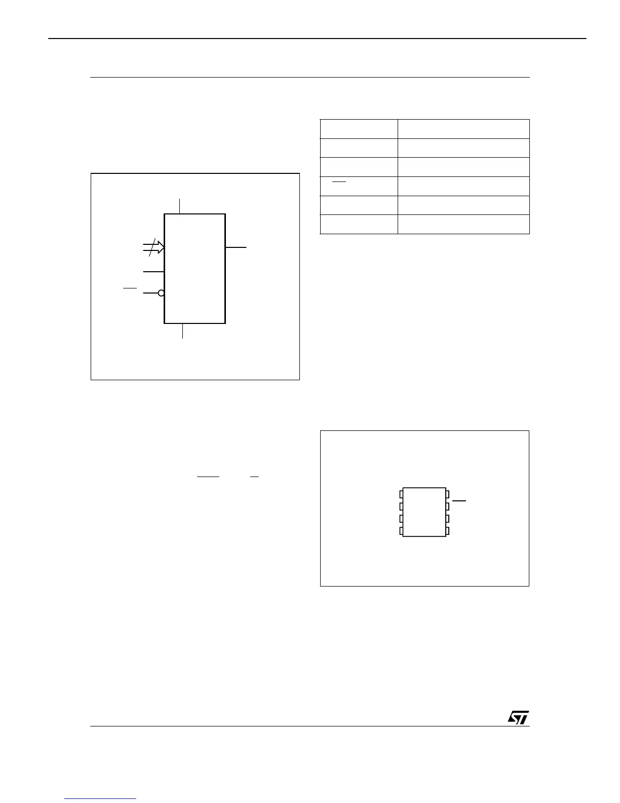
Figure 2. Logic Diagram
I
2
C uses a two-wire serial interface, comprising a
bi-directional data line and a clock line. The devic-
es carry a built-in 4-bit Device Type Identifier code
(1010) in accordance with the I
2
C bus definition.
The device behaves as a slave in the I
2
C protocol,
with all memory operations synchronized by the
serial clock. Read and Write operations are initiat-
ed by a Start condition, generated by the bus mas-
ter. The Start condition is followed by a Device
Select Code and Read/Write
bit (RW) (as de-
scribed in Table 3.), terminated by an acknowl-
edge bit.
When writing data to the memory, the device in-
serts an acknowledge bit during the 9
th
bit time,
following the bus master’s 8-bit transmission.
When data is read by the bus master, the bus
master acknowledges the receipt of the data byte
in the same way. Data transfers are terminated by
a Stop condition after an Ack for Write, and after a
NoAck for Read.
Table 2. Signal Names
Power On Reset: V
CC
Lock-Out Write Protect
In order to prevent data corruption and inadvertent
Write operations during Power-up, a Power On
Reset (POR) circuit is included. At Power-up, the
internal reset is held active until V
CC
has reached
the Power On Reset (POR) threshold voltage, and
all operations are disabled – the device will not re-
spond to any command. In the same way, when
V
CC
drops from the operating voltage, below the
Power On Reset (POR) threshold voltage, all op-
erations are disabled and the device will not re-
spond to any command.
A stable and valid V
CC
(as defined in Table 9. and
Table 10.) must be applied before applying any
logic signal.
Figure 3. DIP, SO, TSSOP and UFDFPN
Connections
Note: See PACKAGE MECHANICAL section for package dimen-
sions, and how to identify pin-1.
AI01844B
3
E0-E2 SDA
V
CC
M24C64
M24C32
WC
SCL
V
SS
E0, E1, E2 Chip Enable
SDA Serial Data
SCL Serial Clock
WC
Write Control
V
CC
Supply Voltage
V
SS
Ground
SDAV
SS
SCL
WCE1
E0 V
CC
E2
AI01845C
M24C64
M24C32
1
2
3
4
8
7
6
5
AVR3600 harman/kardon
 Loading...