Do you have a question about the Harman Kardon hk990Vxi and is the answer not in the manual?
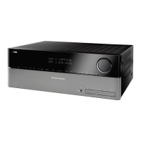
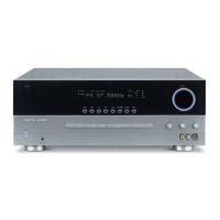
The Harman Kardon hk990Vxi and hk880Vxi are high-voltage, high-current stereo receivers designed to provide thousands of hours of sound and video enjoyment. This manual covers the operating controls, features, hook-up, and operation of both models, with specific information for each noted in bold face.
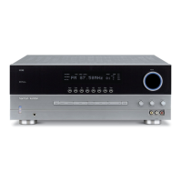
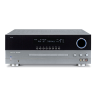
The receiver's front panel features a POWER button (1) to turn the unit on and off, also controlling power to a switched AC outlet on the back panel. A HEADPHONE JACK (2) allows for private listening, with the option to turn off speakers. SPEAKER SELECTORS (3) enable independent selection of two sets of loudspeakers, or both. BASS and TREBLE tone controls (4) adjust sound below 400Hz and above 2000Hz respectively, offering up to ±10dB adjustment without affecting midrange. The BALANCE control (5) distributes sound between right and left speakers, useful for uneven listening positions.
The VCR/TAPE MONITOR selector (6) provides flexibility for routing, switching, and dubbing between multiple VCRs or video sources, in addition to tape playback and recording. It's crucial to return this knob to SOURCE or REMOTE after use to avoid silence from other inputs. The RECORD OUT selector (7) offers remarkable flexibility in choosing sources for video or audio recordings. When set to SOURCE, the signal originates from one of the FUNCTION inputs (TUNER, CD, PHONO, A/V). This allows for simultaneous recording to two devices. For the hk880Vxi, the left and right RECORD OUT positions enable copying between sources connected to the VCR/TAPE inputs. For the hk990Vxi, the left RECORD OUT positions allow copying between two VCRs (1 TO 2 or 2 TO 1), and the right positions for copying between two audio tape decks.
The FUNCTION selector (8) chooses the desired sound source (TUNER, CD, PHONO, A/V). The A/V input is particularly useful for connecting stereo or mono audio outputs from TV tuners, Laser Disc players, MTS adaptors, or stereo TV outputs to the hi-fi system, enhancing video enjoyment. The VOLUME control (9) adjusts the overall sound level. The LOUDNESS button (10) provides a special equalization curve to compensate for decreased bass sensitivity at low listening levels, restoring frequency balance for background music.
The STANDBY light (11) indicates that the main POWER switch is on, even when the unit is turned off by remote control, allowing the receiver to remain in this mode indefinitely. The SUBSONIC filter (12) helps control acoustic consequences of warped records and turntable resonance by reducing sub-bass frequencies at 6dB per octave below 15Hz, preventing amplifier power drain and potential woofer damage. The MONO button (13) combines left and right channel signals, routing their sum to both power amplifier channels, useful for mono records, mono VCR input, and speaker phase testing. The EXTERNAL PROCESSOR switch (14) activates a special "loop" for connecting signal processors like equalizers, Surround Sound processors, or dynamic noise reducers.
For the hk990Vxi, the MOVING MAGNET/MOVING COIL CARTRIDGE input selector (15) allows connection of both MM and MC cartridges. The HIGH CURRENT and HIGH VOLTAGE LEDs (16) indicate the receiver's operating mode. The FM/AM PRESET MEMORY section (17) allows setting and recalling up to 12 FM and 6 AM stations using 6 buttons. The FM/AM selector (18) cycles through preset banks. The MEMORY button (19) is used to enter station memory presets. The TUNER SECTION DISPLAY (20) shows preset groups (FM 1, FM 2, AM), digital frequency, and for the hk990Vxi, an ACTIVE TRACKING indicator. The UP, DOWN, and SEEK TUNING buttons (21) select stations, with SEEK mode scanning for strong signals and MANUAL mode allowing fine-tuning. For the hk990Vxi, ACTIVE TRACKING (22) circuitry increases adjacent FM channel selectivity, useful in areas with many close FM signals.
To begin, power up any signal sources not connected to the receiver's switched convenience receptacle first, then the receiver itself. If using the remote, the front panel POWER button must be pressed in. For a test run, select an input with the FUNCTION selector and play a source.
Setting FM and AM presets involves switching to TUNER, selecting the broadcast band with FM/AM, tuning a station, pressing MEMORY, and then a preset button within eight seconds. The receiver remembers the last station preset.
To play a CD, record, FM, or A/V component, turn on the source, then the receiver. Select the appropriate input with the FUNCTION selector, activate the source, and adjust VOLUME. If using the remote, set the front panel FUNCTION switch to REMOTE.
For audio tape or videocassette playback, turn on the deck/VCR, then the receiver. Select the appropriate VCR or tape input with the VCR/TAPE MONITOR switch, activate the source, and adjust VOLUME. Remember to return the VCR/TAPE MONITOR switch to SOURCE when listening to other inputs.
Recording to a tape deck or VCR involves selecting the recording source with the RECORD OUT knob. This output is then available at the record outputs of the connected devices. Press RECORD on the cassette deck/VCR. To monitor the recording, select the appropriate VCR/TAPE MONITOR position. To listen to another source while recording, return the VCR/TAPE MONITOR to SOURCE and select another input with the FUNCTION switch. To compare source to recording, alternate between the source position and the VCR/Tape monitor knob.
Copying from one tape deck or VCR to another requires selecting the copy "direction" with RECORD OUT. For example, to copy from VCR 1 to VCR 2, load the tape to be copied into VCR 1 and select VCR 1 TO 2. Press RECORD on the receiving device. Monitor the recording by setting the VCR/TAPE MONITOR knob to hear/see the signals from the component making the copy.
Always read and retain instructions. Heed all warnings on the receiver and in the manual. Follow all instructions. Avoid using the receiver near water. Ensure proper ventilation. Do not remove the cover; refer servicing to qualified personnel. The lightning flash symbol warns of un-insulated "dangerous voltage." The exclamation point warns of important operating and maintenance instructions. Do not expose the appliance to rain or moisture to reduce the risk of fire or electric shock.
Avoid heat sources like radiators, stoves, and direct sunlight. Connect to a 120-volt, 60-cycle power supply ONLY. Protect power cords from being walked on or pinched. Clean the cabinet with a clean, dry cloth, or a lightly wet cloth with mild soap and water; avoid volatile solvents. If an abnormal smell or smoke is detected, turn off the receiver and pull the power cord, then contact service. Service is required if the power cord/plug is damaged, objects/liquid enter the receiver, it's exposed to rain, doesn't operate normally, or is dropped/damaged.
Replace both AA (1.5V/R6/UM3) batteries simultaneously when the operating range shortens. Ensure the remote's infrared lens and the receiver's REMOTE SENSOR window are clean. Avoid using the remote near fluorescent lamps. Remove batteries if not using the remote regularly to prevent damage.
Use high-quality speaker cables of appropriate gauge for the distance. Ensure both right and left speaker wires are the same length. Avoid coiling excess wire near line-level hook-up cords. Match polarity (positive to positive, negative to negative) when connecting wires to terminals. Strip 1/2 inch of conductor, twist strands, and insert into the terminal hole, ensuring no loose strands cause a short circuit.
If using two sets of speakers, consult APPENDIX I for multiple speakers in parallel. Set the SPEAKER OPERATING MODE switch to 4-ohm position for 4 or 6-ohm speakers, and 8-ohm for 8-ohm speakers. If in doubt, use 4-ohm mode to prevent overheating. The receiver has a thermal protection circuit that temporarily shuts off power if internal temperature is too high, automatically resuming when cooled.
Attach FM antenna to 300 Ω BAL or 75 Ω UNBAL terminals. Connect external AM antenna ground wire to GND terminal. A roof-top FM antenna mast should be grounded directly to earth ground. The quality of reception depends on the antenna used. For "problem" areas or better reception, refer to Appendix II.
Save all packing material for future shipping. Fill out the warranty card and save your sales receipt as proof of ownership and warranty start date.
The receivers are fully shielded and can be placed on top of or under other stereo components, ensuring 3/8-inch clearance for cooling.
Connect the turntable's ground wire to the receiver's GROUND terminal to prevent hum.
Ensure the receiver and all other components are switched off. Match left and right component plugs with the corresponding input jacks (red for right, grey/black/white for left).
The receiver has one switched and one unswitched 120V convenience receptacle. Use switched outlets for components used each time the stereo system operates, and the unswitched for other components rated 180 watts or less, such as a VCR.
| Type | Stereo Receiver |
|---|---|
| DAC Resolution | 24-bit/192kHz |
| Total Harmonic Distortion | 0.03% at 150W |
| Power Output | 150W into 8 Ohms (20Hz - 20kHz, <0.03% THD) |
| Inputs | 6 analog, 4 digital (2 coaxial, 2 optical) |