Do you have a question about the Harman Kardon HKTS 200/230 SUB and is the answer not in the manual?
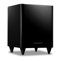
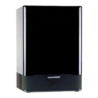
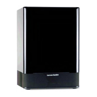
| Subwoofer Type | Powered |
|---|---|
| Amplifier Power | 200 watts |
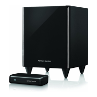
| Inputs | LFE (RCA) |
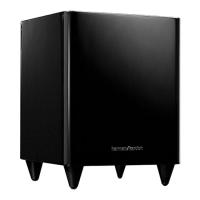
| Finish | Black |
| Enclosure Type | Bass-reflex |
| Driver Size | 8-inch |
| Dimensions (H x W x D) | 353mm x 267mm x 267mm |
| Weight | 9.0 kg |
Controls automatic turn-on/standby based on audio signal presence.
Troubleshooting steps for no sound from any, one, or center speakers.
Detailed schematic of the power supply and control sections of the HKTS 200SUB.
Schematic detailing the power supply and AC/DC conversion stages.
Schematic showing control ICs, voltage regulators, and protection circuits.
Schematic illustrating the Pulse Width Modulation controller and related components.
Schematic for the digital interface, DSP, and audio processing components.
Schematic showing audio input stages, control switches, and LED indicators.
Schematic detailing the Low-Frequency Effects (LFE) switch circuit.