Harman® • P42i Pellet Insert Installation Manual • 2023 -___ • 08/2324 8742-901D
Align the top center surround section between the right and
leftpanelsandtightenthefour1/4”nutstolockitinplace.
Now tighten the 3 bolts and nuts on the left and right side
panels.
Unboltthemountingframefromtheshippingpalletusinga
1/2”socketonthethreelagscrews;thelagscrewsandthe
pallet will not be reused and can be discarded.
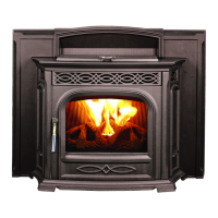
Install the outside air pipe stub [if used], to the mounting
frame. Figure 5.9.
Theunitcomesstandardwitha4”(1-00-574034)pipestub.
1. Part#1-00-574100isforusewith4”PLventstarterpipe
andpart#1-00-574034for4”StainlessSteelexpipe.
Theuestubassemblybaseisaroundplatewhichallowsit
toswiveltoallowtheuepipetoexitthemountingframein
other positions rather than straight up. Figure 5.10.
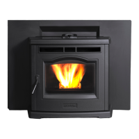
Inserting the Power Cord
ThepowercordcanbeinsertedintotheLineFilterlocated
behind the side panel. Figure 5.11.
Figure 5.10Figure 5.9
Note: If installing the optional wing extension it must be
installed before completing the following steps.
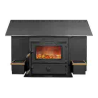
With the surround attached, install the coupler nut weldments
to the frame in the hole location that suits your needs with
the(4)1/4-20x5/8angescrews and nuts and1/2”jack
bolts.Installthe(4)5/16”-18levelingboltsintothethreaded
holes in the bottom pan of the mounting frame, install the
mounting frame into the opening and adjust these bolts to
insuretheframeis level.(Note:Useof all4levelingbolts
maynotbenecessary.)Tightenthe1/2”jackboltsagainstthe
lintel.SeeFigure5.12.
Figure 5.12
1/2" threaded jack bolts &
couplerweldmentand1/4-20x
5/8”Flangebolts
Anchor bolt holes are
innernon-threaded
holes
Levelingboltholes
are outer, threaded
holes.
Figure 5.11
ROUTE POWER CORD AWAY FROM THE APPLIANCE.
DO NOT RUN CORD UNDER OR IN FRONT OF THE
APPLIANCE.
WARNING
Connect the venting system and outside air system [if
used],tothepipestub(s)onthemountingframe,following
theproceduresdetailedin“Section4:TerminationLocation
andVenting”.Ifoutsidecombustionairwillbeusedonthe
unit,becertaintoinstalltheHarman®OutsideAirAdapter
P/N 1-00-574350 ontotheunit before installingit into the
mounting frame.
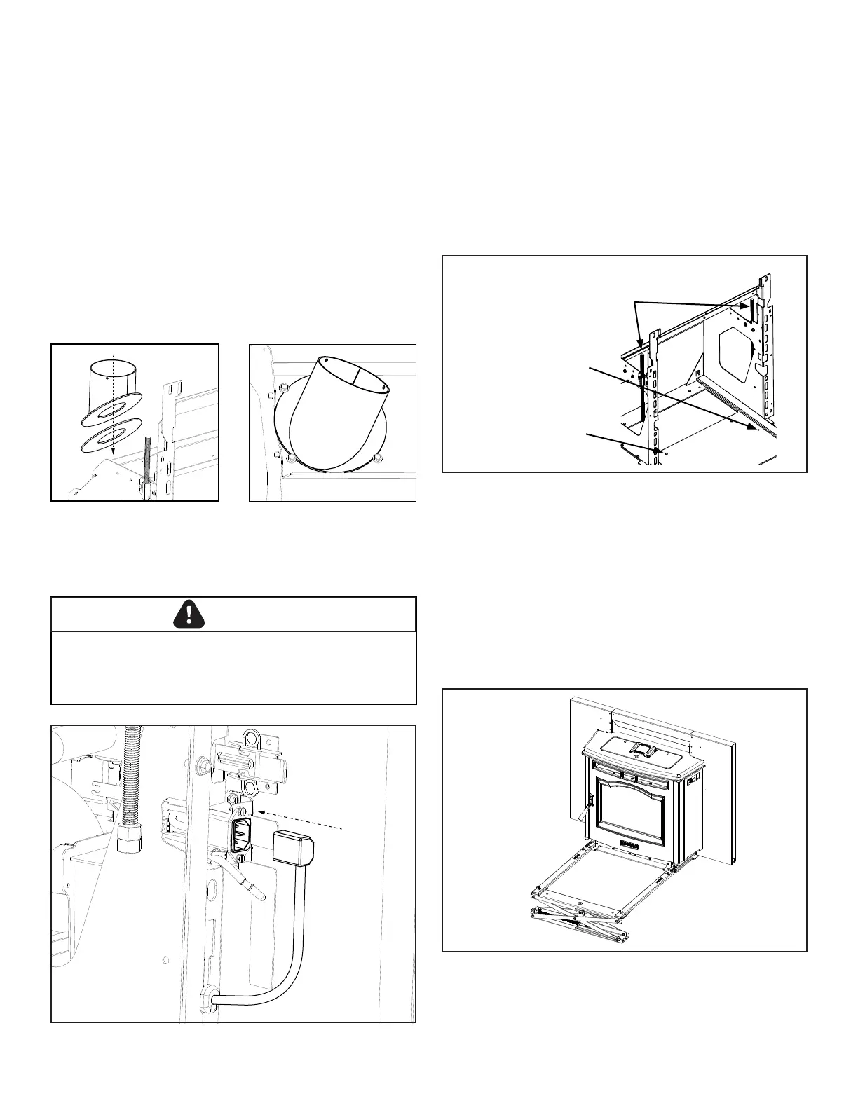
InstalltheoptionalServiceRailKittothemountingframe.
Place the unit on the service rail leaving enough room to
gain access to the wiring. Figure 5.13.
Figure. 5.13
 Loading...