Do you have a question about the Harmonic NSG 9000-3G and is the answer not in the manual?
Details physical dimensions, weight, power supply options, consumption, and environmental specs for the NSG 9000.
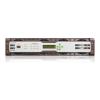
Describes components on the NSG 9000 front panel like bezel, LEDs, control panel, and cooling fans.
Details the components on the NSG 9000 back panel, including module slots, ports, and power supplies.
Details qualified AC/DC power supply options, part numbers, and supported QAM channels per RF port.
Describes the main processing module, its interfaces (GbE, DTI, ASI), and its swappable nature.
Details the nine module slots on the back panel that accommodate QAM-RF modules.
Explains the two hot-swappable power supply units, their dimensions, and status LEDs.
Details the six GbE ports, their specifications, and supported connector types (SFP, RJ-45).
Describes SFP modules for converting optical to electrical data, supporting various physical interfaces.
Details the QAM-RF modules, their ports, upconverter technology, and RF port specifications.
Provides instructions for installing the NSG 9000 platform in a rack, covering specifications and mounting.
Explains the procedure for inserting processing and QAM-RF modules, emphasizing ESD precautions.
Specifies requirements for installing the 2-RU chassis in a standard EIA 19-inch computer rack.
Covers redundant power supply setup, wiring, and overcurrent protection requirements for the NSG 9000.
Guides on installing an optional DTI card for M-CMTS applications, including ESD precautions.
Covers connecting AC and -48 VDC power supplies, including grounding and power-up sequences.
Guides on how to hot swap power supply units in the platform, covering removal and installation procedures.
Details the quick hot-swap procedure for fans, emphasizing the time limit to avoid device damage.
Details connecting the DC input power cable to the NSG 9000 back panel and securing it with a safety bracket.