2
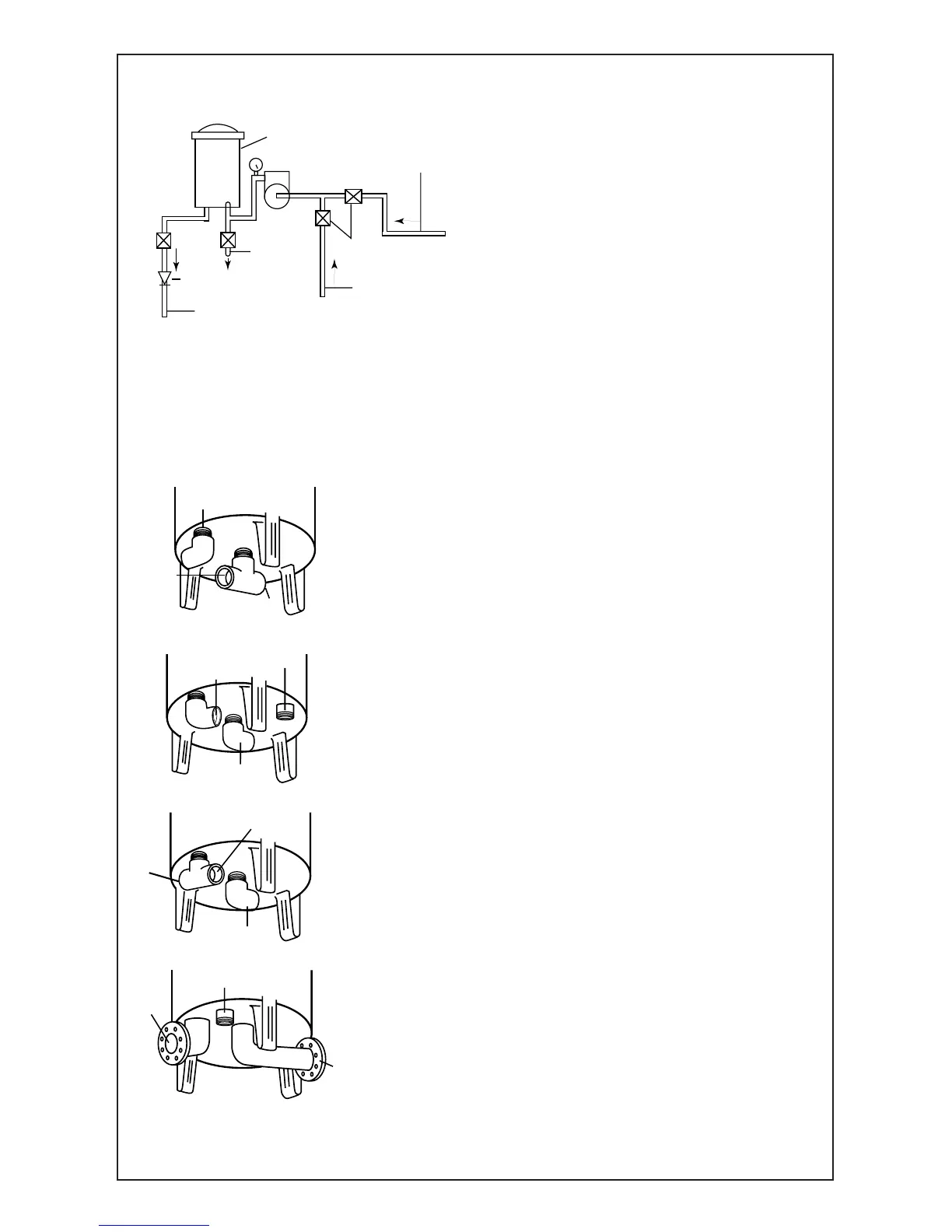
TYPICAL INSTALLATION OF RESIDENTIAL POOLS
Where unit is being installed below water
level of the pool, it is necessary to pro-
vide valves as indicated in the drawing
as shown, so that the filter housing may
be opened without draining the pool.
To protect against electrolysis, all
metal components of the water circu-
lation and heating systems must be
connected by a wire to ground the entire
system.
Filter housings must be grounded
DO NOT STORE CHEMICALS NEAR FILTER HOUSING
TYPICAL INSTALLATIONS*
For Residential and Commercial Pools
SUGGESTED INSTALLATION (Fig. 1)
1. Install 1-1/2" "T" on the center nipple as
shown in figure 1.
2. Pipe water from discharge of pump to one
side of this "T".
3. Install a 1-1/2" x approximately 10" nipple
from other side of this "T" with 1-1/2"
valve at end of nipple. This is for draining
filter unit.
4. Install 1-1/2" elbow on the other nipple as
illustrated. This is the return-to-pool line.
SUGGESTED INSTALLATION (Fig. 2)
1. Install 2" thread to socket PVC elbows on
side of nipple marked inlet–Pipe water from
pump discharge to this elbow.
2. Install 2" thread to socket PVC elbow on
center nipple marked outlet. This is the
return to pool line.
3. Install 1" valve or cap on marked drain.
SUGGESTED INSTALLATION (Fig. 3)
1. Install thread to socket "T" on the side
nipple as shown in figure 3. Pipe water from
discharge of pump to one side of this "T".
2. Install nipple and valve in other side of this "T".
This is the drain for emptying filter housing.
3. Install thread to socket PVC elbow on
center outlet. This is the return-to-pool line.
SUGGESTED INSTALLATION (Fig. 4)
1. Install water pipe from the pump to flange
marked "inlet".
2. Pipe return-to-pool line flange marked "outlet".
3. Install valve in drain line to threaded
nipple marked "drain".
 Loading...