5
SINGLE AND MULTIPLE BETTERFILTER
®
COMMERCIAL INSTALLATION
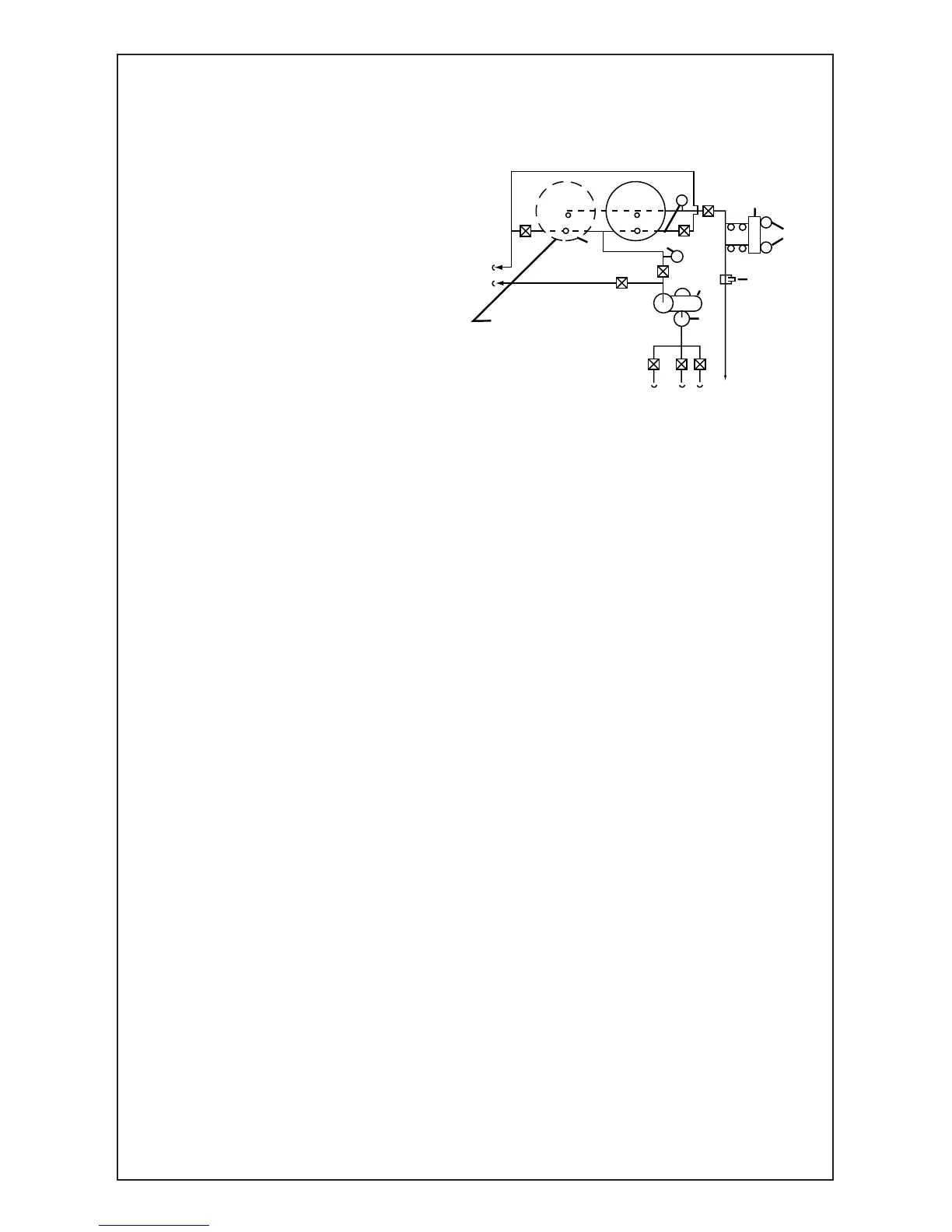
Schematic Diagram of Typical
Commercial Pool Installation
A. Main Drain Line Valve
B. Vacuum Cleaning Valve
C. Return-to-Pool Valve
D. Pump-to-Filter Valve
E. Pump-to-Drain Valve
F. Filter Drain Valves
G. Skimmer LIne Valve
1. Filter Housing(s)
2. Pressure Gauges 2-1/2"
Face–0-60 PSI
3. Flow Rate Indicator-
Post Filter
Installation Required
4. Pump and Motor
5. Hair and Lint Strainer
-To Meet Code
Requirements
6. Chemical Crocks
7. One Double or Two
Single Head Feeder
8. Filter Housing
Drain Line
9. Pool Main Drain Line
10. Pool Vacuum Line
11. Return to Pool Line
12. Skimmer Line
1. Turn off pump. 2. Drain filter hous-
ing. 3. Unscrew wing nuts. 4. Lift lid
from filter. 5. Remove top stainless
steel plate from unit. 6. Take off top
rubber seal. 7. Lift out cartridge lifters
(with cartridges) from filter housing.
8. Clean cartridges (See cover for
cleaning instructions). 9. Return car-
tridge lifters (with cartridges) to hous-
ing. 10. Re-place rubber top seal
properly. 11. Put stainless steel plate
in place. 12. Replace lid. 13. Grease
studs. 14. Replace wing nuts, alter-
nately tightening nuts on opposite
sides. 15. Close drain valve. 16. Put
filter back service.
All Filter Housings Must Be Grounded
To protect against electrolysis, all metal components
of the water circulation and heating systems must
be connected by a wire to ground the entire system.
HOW TO REMOVE AND REPLACE CARTRIDGES ON
BETTERFILTERS 168, 252, 336, 450, 600, 900FL, 1200FL
DO NOT STORE CHEMICALS NEAR FILTER HOUSING
 Loading...