5718 52nd Street Kenosha WI 53144|Orders and Customer Care: 1-866-616-1270|Fax: 1-866-616-1271|HarrisPoolProducts.com
CHAPTER 1:
IMPORTANT SAFETY INSTRUCTIONS
READ AND FOLLOW ALL INSTRUCTIONS
1. The Sand Filters are designed to work with water
at a temperature from 32ºF and 113ºF. The
lter should never be operated outside of these
temperatures or damage may occur.
2. The installation should be carried out in accordance
to the safety instructions of swimming pools and
the specic instructions for each facility.
3. The user should make sure that the installation is
carried out by qualied authorized persons and that
these persons have rst carefully read the following
instructions. Incorrectly installed equipment may
fail, causing severe injury or property damage.
4. The operating safety of the lter is only guaranteed if
the installation and operation instructions are
correctly followed.
5. To reduce the risk of injury, do not permit children
to use this product.
6. Incorrectly installed equipment may fail, causing
severe injury or property damage.
7. Chemical spills and fumes can weaken Swimming
Pool or Spa. Corrosion can cause lters and other
equipment to fail, resulting in severe injury or
property damage. Do not store pool chemicals near
your equipment.
8. Any modication of the lter requires the prior
consent from the supplier’s original replacement
parts and accessories authorized by the
manufacturer ensure a high level of safety. The
supplier assumes no liability for the damage and
injuries caused by unauthorized replacement parts
and accessories.
Sand Filtration System Working Principle
Incoming water from the piping system is automatically
directed by the Multi-Port Valve to the top of the lter
bed. As the water is pumped through the lter sand,
dirt and debris are trapped by the lter bed, and ltered
out. The ltered water is returned from the bottom of
the lter tank, through the Multi-Port Valve and back
through the piping system.
CHAPTER 2: PREPARATION BEFORE INSTALL
▲WARNING This product should be installed and
servicedonlybyaqualiedprofessional.
1.
Position the lter next to the Swimming Pool or Spa.
2. The lter should be placed on a level concrete
slab, very rm ground, or equivalent. Ensure that
the ground will not subside, preventing any strain
from the attached plumbing.
3. Position the lter so that the piping connections,
Multi-Port Valve and winter drain is convenient and
accessible for operation, servicing and winterizing.
4. Ensure that the compliance label is facing the
front to allow easy identication in the case of
service difculties.
CHAPTER 3: INSTALLATION INSTRUCTIONS
▲WARNING This product should be installed and
servicedonlybyaqualiedprofessional.
1. Put the lter tank on the base. Turn the lter tank to
the right to tighten it. Position the outlet drain plug
so it is facing outside for easy operation.
2. Before lling the lter media into the lter vessel, do
a visual check of the laterals. Look for broken or
loose laterals. Replace if necessary. The laterals of
side-mount valve sand lter are all installed.
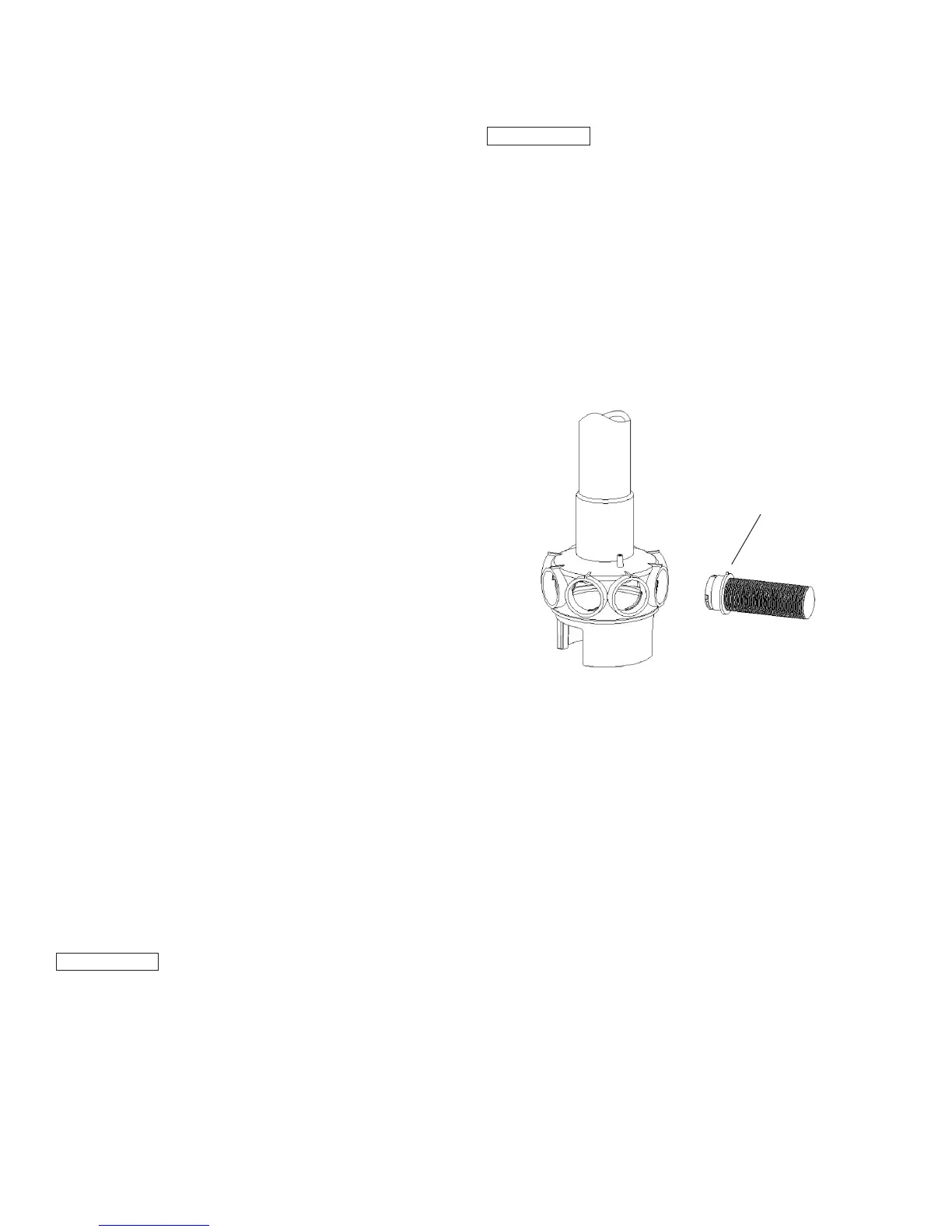
3. Match the Raised Point of the laterals to Folding
Umbrella lateral holder, insert the laterals and turn
90º clockwise. Listen for a sound to conrm the
lateral is in place. Please refer to following picture.
4. Make sure the air release hose is running along
side the body of the lateral holder. One end of the
air release hose MUST be out of the sand. DO
NOT bury the air release hose in the sand.
5. To eliminate stress on the laterals, ll the lter
vessel with enough water to provide a cushioning
effect when the lter sand is poured in.
6. Use the clear clamshell cover to protect the lter
top mount and make sure the central stem pipe has
been fully covered.
7. Carefully pour the exact amount of sand into the
lter vessel (see sand lter tank label for amount
or chapter 9 of this manual). DO NOT allow sand
to go into the stem pipe. DO NOT damage the lter
top mount or it can cause a leak.
8. Put the O-Ring on the the top mount valve and
then connect the valve on the lter vessel. The
stem pipe should be straight and aligned with the
top mount valve. Tighten the ange clamp on the
valve. NOTE: The ange clamp should be in place
and tight or it could cause injuries.
Raised Point
 Loading...