5718 52nd Street Kenosha WI 53144|Orders and Customer Care: 1-866-616-1270|Fax: 1-866-616-1271|HarrisPoolProducts.com
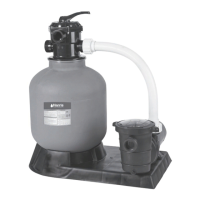
9. To connect the pump to the base, use the screws
from the pump hardware pack. Use the pump
manual to install the and operate the pump.
10. Adjust the valve position. The white pressure hose
connects to the pump output/input valve.
11. The other two connection ends of the valve connect
to the swimming pool and the drain outlet hose.
Installation Notes
1. Make sure the lter is worked under the work
pressure and using a pressure control valve when
the system is using a booster pump.
2. If the pump position is higher than the water level,
it requires to install the back water control valve.
3. If the pump position is lower than the water level,
it requires installing an isolation valve.
4. Minimize the length of pipe and the number of
ttings to minimize friction loss to ensure maximum
efciency.
5. Connect all plumbing to the Multiport Valve taking
care that all joints are glued or tightened securely
to prevent leaking.
6. To prevent breakage and damage to the pump and
Multiport Valve, use only pipe sealants specically
formulated for plastics.
7. Ensure solvents are not excessively applied to
ttings as this could run into O-Rings and create
sealing problems.
8. Do not over tighten ttings or adapters.
InstallationoftheMultiportValve
Top Mount Sand Filters are supplied with a screw
down
Multiport Valve. Supplied with the Multiport Valve are
Flange clamp, screws and O-Ring.
1. Screw the barrel unions onto the threaded ports on
the Multiport Valve.
2. When rotating the Multiport Valve into position
on a Top Mount Filter, leave some leeway for better
alignment of plumbing.
3. Once the Multiport Valve is in position and the
plumbing is aligned, apply the thread tape to the
barrel union thread.
4. Using the roll of Teon tape wrap the Teon tape
around the thread (tail) of the barrel union in a clock
wise direction.
5. Screw the barrel union into the thread of the
Multiport Valve and hand tighten. The barrel union
should be rmly threaded into the Multiport Valve
and there should be no play between the thread.
6. Once you have done this tighten the barrel union
with an appropriate tool until it is tight.
7. Repeat steps until all barrel unions are rmly onto
the Multiport Valve.
8. Glue the plumbing to the Barrel unions and allow
24 hours for glue (solvent) to set before starting
the lter.
9. Test the lter and check for leaks around the
threads. If leaking occurs disconnect plumbing and
repeat the steps 2 to 6 until the leak has stopped.
CHAPTER 4: INITIAL STARTUP OF FILTER
Be sure correct amount of lter media is in tank and
that all connections have been made and are secure.
1. Depress Multiport Valve handle and rotate to the
BACKWASH position. NOTE: To prevent damage
to control valve seal, always depress handle
before turning.
2. Switch on the Pump. Open the Inlet Valve allowing
the lter tank to ll with water. CAUTION: All
suction and discharge valves must be open
when starting the pump. Failure to do so could
cause severe personal injury and/ or property
damage. NOTE: If a pump is installed, switch the
pump on and off, instead of closing and opening
the Inlet Valve.
3. Once water ow is steady out the waste line, run
the pump for at least one minute. The initial
backwashing of the lter is recommended to
remove any impurities or ne sand particles in the
lter media.
4. Turn the pump off. Set the Multiport Valve to the
RINSE position. Switch on the Pump. Open the
Inlet Valve until water in sight glass is clear -
approximately 10 to 15 seconds.
5. Switch off the Pump. Close the Inlet Valve, set the
Multiport Valve to the FILTER position and Switch
on the Pump. Open the Inlet. Your lter is now
operating in the normal lter mode.
6. Adjust pool suction and return valves to achieve
desired ow. Check the plumbing and lter for water
leaks and tighten connections, bolts, and nuts, as
required. NOTE: During initial clean-up of the
pool water, it may be necessary to backwash
frequently due to the unusually heavy initial dirt
load in the water.
7. Record the pressure gauge reading (start up
pressure) during initial operation. After a period
of time, the accumulated dirt and debris in the lter
causes a resistance to ow, and the ow diminishes.
The pressure will start to rise and the ow of
water will start diminishing. When the pressure
gauge reading is 8-10 PSI higher than the
initial “Start up” pressure, it is time to backwash
(clean) the lter (see Backwashing). NOTE: To
prevent unnecessary strain on piping system
and valving, always shut off the pump before
switching lter control valve position. To
prevent damage to the pump and lter and
for proper operation of they system, clean
pump strainer and skimmer baskets regularly.

 Loading...