5000/5100 Series Digital Analog Clocks Installation and Operation Manual 19
Chapter 2: ADC-5100 Series Analog Digital Clocks
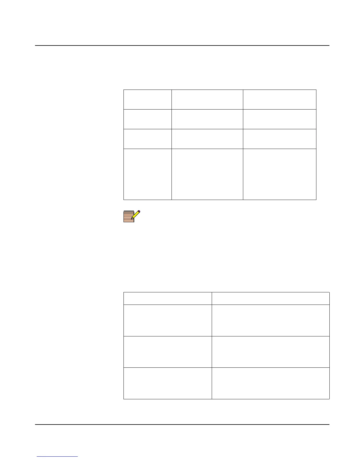
Table 2-9 provides information about clock wall mounting
specifications
Note
A convenient template drawing showing the correct mounting centers
is included with the clock.
Clearances
Table 2-10 lists the minimum clearances, measured in inches, from the
mounting keyhole centers to the outside edge of each clock:
Table 2-9. Clock Wall Mounting Specifications
Clock
Overall
Dimensions
Mounting Keyhole
Centers
ADC-5116 17.5×17.5 in. 16.0×15.5 in.
(4 keyholes)
ADC-5112 14.0×14.0 in. 12.0×10.5 in.
(4 keyholes)
ADC-5108 10.5×10.5 in. 8.0×7.75 in.
(3 keyholes).
The bottom single
keyhole is located 0.35
in. to the right of the
center line.
Table 2-10. Clock Clearances
Clock Clearances (Inches)
ADC-5116
• Top edge 0.813
• Sides 0.75
• Bottom edge 1.187
ADC-5112
• Top edge 1.125
•Sides 1.0
• Bottom edge 2.375
ADC-5108
• Top edge 0.875
• Sides 1.250
• Bottom edge 1.875
 Loading...