I
CONTROLS AND INDICATORS
TALK
/
MONITOR SWITCH.
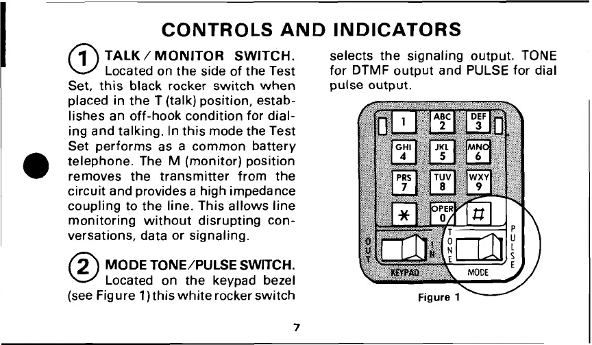
selects the signaling output. TONE
Located on the side of the Test for DTMF output and PULSE for dial
Set, this black rocker switch when pulse output.
placed in the T (talk) position, estab-
lishes an off-hook condition for dial-
ing and talking. In this mode the Test
Set performs as a common battery
telephone. The
M
(monitor) position
removes the transmitter from the
circuit and provides a high impedance
coupling to the line. This allows line
monitoring without disrupting con-
versations, data or signaling.
0
MODE TONE/PULSE SWITCH.
Located on the keypad bezel
(see Figure
1)
this white rocker switch
TCI Library: www.telephonecollectors.info