Do you have a question about the Harsco Industrial C1500H and is the answer not in the manual?
Installation, operation, and service must adhere to manual instructions and qualified personnel.
Proper training is essential for preventing accidents during installation and service.
Customer responsibility to maintain safety features like guards, labels, and controls.
Definitions of DANGER, WARNING, CAUTION, and NOTICE signal words used in the manual.
Warnings about electrical shock, lockout/tagout, and water contact with electrical components.
Precautions against fire, explosion, incorrect fuels, and hot surfaces during operation.
Warnings regarding lifting hazards and proper equipment to lift and position the boiler.
Precautions related to cleaning products and condensate handling.
Warnings about hot fluids and annual testing of the safety relief valve.
Precautions to prevent tripping, slipping, and falling hazards around the boiler.
Instructions for inspecting the boiler upon arrival and proper storage before installation.
Requirements for conforming to national, state, and local codes for installation.
Guidelines for providing a firm, level foundation and proper placement of the boiler.
Minimum clearances from combustible surfaces and for service access.
Instructions for making electrical connections to the boiler.
Details on power connections for C3000/C4000 models and transformer configuration.
Details on power connections for C1500H/C2000H/C2500 models.
Description of terminal assignments for high voltage circuits on TB2.
Description of terminal assignments for low voltage circuits on TB1.
Information on combustion air requirements and duct fabrication.
Applicable codes and standards for venting gas-fired appliances.
Table of acceptable materials for vent adapters and category II motorized dampers.
Definitions of Category II, Category IV, and Direct Vent appliance categories.
Information on combustion air requirements and duct fabrication.
Requirements for combustion and ventilation air openings based on NFPA 54/ANSI Z223.1.
Requirements for combustion and ventilation air openings based on CAN/CSA B149.1.
Guidelines for flue venting and limitations on vent materials.
Parameters for vent sizing and design, including friction resistance and stack temperature.
Required clearances for vent terminations from structures and openings.
Instructions for connecting the flue and managing condensate drainage.
Guidelines for vent termination locations and clearance requirements.
Considerations for designing venting systems for multiple boilers.
Information on sealed combustion air intake and exhaust vent configurations.
Instructions for connecting the combustion air supply duct to the boiler inlet collar.
Steps for safely removing an existing boiler from a common venting system.
Guidelines for gas piping hook-up, pressure testing, and materials.
Procedures for pressure testing gas piping and ensuring leak-free connections.
Chart and graph detailing water flow rates and pressure drop for various boiler models.
Configuration advice for controlling boiler temperature in refrigeration machine systems.
Requirements for preventing gravity circulation in air handling unit systems.
Details on strainers, relief valves, drains, and condensate piping.
Procedures and precautions for flushing and filling the boiler system.
Items to verify before attempting to start the boiler.
Checks for safety systems that must be performed before normal operation.
Procedure to test the ignition system safety shutdown sequence.
Procedure to test the boiler's low water cut-out functionality.
Procedure to test the boiler's high-limit control function.
Procedures to test low and high gas pressure switches.
Overview of the ENVI® control interface and basic navigation.
Overview of the ENVI® control interface and basic navigation.
How to view and change the boiler's supply temperature setpoint.
Table of other adjustable Comfort Heat parameters and their factory settings.
Description of other parameters for DHW, Boiler Settings, and OEM Settings.
Brief descriptions of the main menu items: Standby, Information, Errors, etc.
Description of available test modes for service technicians.
Overview of gas/air ratio control and blower speed for optimal performance.
Steps for setting combustion using test modes and a combustion analyzer.
Procedures for adjusting the gas valve for high and low fire combustion.
How to view the flame signal strength using the control panel.
Basic principles of boiler operation and familiarization with controls.
Information on factory tests performed to ensure performance criteria were met.
Steps for normal boiler startup and shutdown.
Step-by-step guide for starting up the boiler.
Instructions for switching between natural gas and propane fuels.
Steps for safely shutting down the boiler during normal operation.
Instructions for emergency shut-off, including when gas supply fails.
Table of operating conditions, including input rating, voltage, amperage, and gas flow rates.
Schedule for daily, weekly, monthly, semi-annual, and annual maintenance tasks.
Daily checks for airflow, operating temperature, and general conditions.
Weekly observation of the main flame condition.
List of monthly checks including flame signal, control tests, and condensate system.
Semi-annual checks including burner cleaning, pH check, and condensate system inspection.
Annual checks including inlet screen, burner, heat exchanger, and component replacement.
Step-by-step guide for safely removing, cleaning, and reinstalling the burner.
Warning and procedure for removing the heat exchanger, performed by experienced personnel.
Steps to follow after completing repairs or maintenance before restarting.
Detailed explanation of the boiler's ignition and firing sequence.
Procedure for addressing boiler issues related to a loss of electrical power.
How to resolve the low water level lockout error and its causes.
Procedure for resolving low gas pressure errors and lockouts.
Procedure for resolving high gas pressure errors and lockouts.
How to address high water temperature lockouts and manual reset requirements.
Diagnosing and resolving errors related to improper airflow through the boiler.
Procedure for addressing ignition failures and flame loss during operation.
Diagnosing flame errors potentially caused by gas valve or detector issues.
Resolving errors related to blocked flues or high exhaust back pressure.
List of manual reset error codes, their internal numbers, and descriptions.
List of auto-reset error codes, their lockout numbers, and descriptions.
Electrical diagrams for various MACH® boiler models and configurations.
Electrical wiring diagram for MACH® C1500H and C2000H boilers.
Electrical wiring diagram for the MACH® C2500 boiler.
Electrical wiring diagram for C3000/C4000 boilers (240VAC).
Electrical wiring diagram for C3000/C4000 boilers (480VAC).
Electrical wiring diagram for dual fuel C1500H/C2000H GG boilers.
Electrical wiring diagram for the C2500GG dual fuel boiler.
Electrical wiring diagram for dual fuel C3000GG/C4000GG boilers (240VAC).
Electrical wiring diagram for dual fuel C3000GG/C4000GG boilers (480VAC).
Wiring diagram for dual fuel control components and gas valves.
Assignments for power block terminal connections on various boiler models.
Detailed breakdown of terminal assignments for the high voltage circuit (TB2).
Detailed breakdown of terminal assignments for the low voltage circuit (TB1).
Transformer wiring diagram for 208VAC, three phase service.
Transformer wiring diagram for 240VAC, three phase service.
Transformer wiring diagram for 480VAC, three phase service.
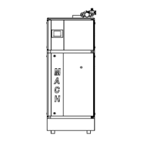
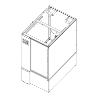
Diagrams identifying major boiler components and parts.
Assembly diagram identifying parts for C1500H/C2000H NG, Propane, and Dual Fuel boilers.
Assembly diagram identifying parts for C2500/C3000/C4000 NG, Propane, and Dual Fuel boilers.
Diagram identifying components of the control panel for all MACH® boiler models.
Diagram identifying components of the control panel for dual fuel MACH® boiler models.
Diagram identifying major components of the heat engine for C1500H/C2000H.
Diagram identifying major components of the heat engine for C2500/C3000/C4000.
Diagram identifying components of the natural gas train for C1500H/C2000H.
Diagram identifying components of the dual fuel gas train for C1500H/C2000H.
Diagram identifying components of the natural gas train for C2500/C3000.
Diagram identifying components of the dual fuel gas train for C2500GG/C3000GG.
Diagram identifying components of the natural gas train for C4000.
Diagram identifying components of the dual fuel gas train for C4000GG.
Form for recording factory and field fire test data for boiler performance.
Log for recording routine maintenance activities and parameters.
Schedule for reducing boiler input rating at higher elevations.
| Brand | Harsco Industrial |
|---|---|
| Model | C1500H |
| Category | Boiler |
| Language | English |