4A
1
Aux input voltage calibration
$204B ――― $205E P-sensor data, ordered according to the resistance(0.1Ω) from big to small and resistance-related
value-resistance
$205F ――― $2072 T-sensor data, ordered according to the resistance(0.1Ω) from big to small and resistance-related
value-resistance
$2073F ――― $2086 oil position sensor, ordered according to the resistance(0.1Ω) from big to small and resistance-
related value-resistance.
Note: fault code table
Code Fault Code Fault
0 NO ERROR 10 BATTERY LOW
1 NO PICKUP 11 CHARGE FAILURE
2 OVER SPEED 12 V LOW
3 UNDER SPEED 13 V HIGH
4 O-SENSOR OPEN 14
5 LOW OILPRESS 15
6 T-SENSOR OPEN 16 I HIGH
7 COOLANT TEMP 17
8 START FAIL 18
9 STOP FAIL
19
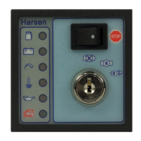
11 Preparations
11.1 To confirm that the controller has installed and fixed properly, and the installation ambient must accord with
installation demand
11.2 To confirm the whole connecting of control lines accord to the electric norm, and confirm to the typical connecting
diagram of “1.3”. Especially the DC power supply must add fusing element safety wire to protect, and the polarity must be
right. Otherwise, it will destroy the controller
11.3 The controller must be ground to the earth properly.
11.4 We suggest that the operators install the “ E- stop” key outside. Connecting the “E-stop” output terminal to the normal
contact of “E-stop” key, and the other point of contact must connect to the anode of working source.
11.5 Putting through the DC working source, confirming the preset parameter accord with actual running requirements.
Such as: current ratio, mode of speed sensor, mode of pressure sensor, mode of temperature, etc.
11.6
If the speed sensor is magnetic speed sensor, we must adjust speed measuring parameter
according to the following steps.
Method 1:
 Loading...