12
Figure 16.
Reset button for
overheating limiter
Abbildung 16.
Rücksetzknopf des
Überhitzungsschutzes
*) For thermostat/ Zur Thermostat: 4 x 0,25 – 4 x 0,5 mm
2
(T170)
Table 3.
Tabelle 3.
Type Power Cables/Fuses
Typ Leistung Kabel/Sicherungen
kW
mm
2
A
mm
2
mm
2
mm
2
M45E, KV45E, KIP45E 4,5 5 x 1,5 3 x 10 5 x 1,5 4 x 0,25 (* 3 x 1,5
M60E, KV60E, KIP60E 6,0 5 x 1,5 3 x 10 5 x 1,5 4 x 0,25 (* 3 x 1,5
M80E, KV80E, KIP80E 8,0 5 x 2,5 3 x 16 5 x 2,5 4 x 0,25 (* 3 x 1,5
M90E, KIP90E 9,0 5 x 2,5 3 x 16 5 x 2,5 4 x 0,25 (* 3 x 1,5
K9, T9 9,0 5 x 2,5 3 x 16 5 x 2,5 4 x 0,25 (* 3 x 1,5
K10,5, T10,5, F10,5 10,5 5 x 2,5 3 x 16 5 x 2,5 4 x 0,25 (* 3 x 1,5
K11G 11,0 5 x 2,5 3 x 16 5 x 2,5 4 x 0,25 (* 3 x 1,5
K12 12,0 5 x 4,0 3 x 20 5 x 2,5 4 x 0,25 (* 3 x 1,5
K13,5G 13,5 5 x 6,0 3 x 25 5 x 2,5 4 x 0,25 (* 3 x 1,5
K15, F15, K15G 15,0 5 x 6,0 3 x 25 5 x 2,5 4 x 0,25 (* 3 x 1,5
For unit
Zum Steuergerät
Fuses
Sicherungen
Power supply
cable to heater
Anschlusskabel
zum Ofen
(HO7RN-F)
For thermostat
Zur Thermostat
For Light/
Added control system
Zur Licht/Zusatzsteuerung
(SSJ)
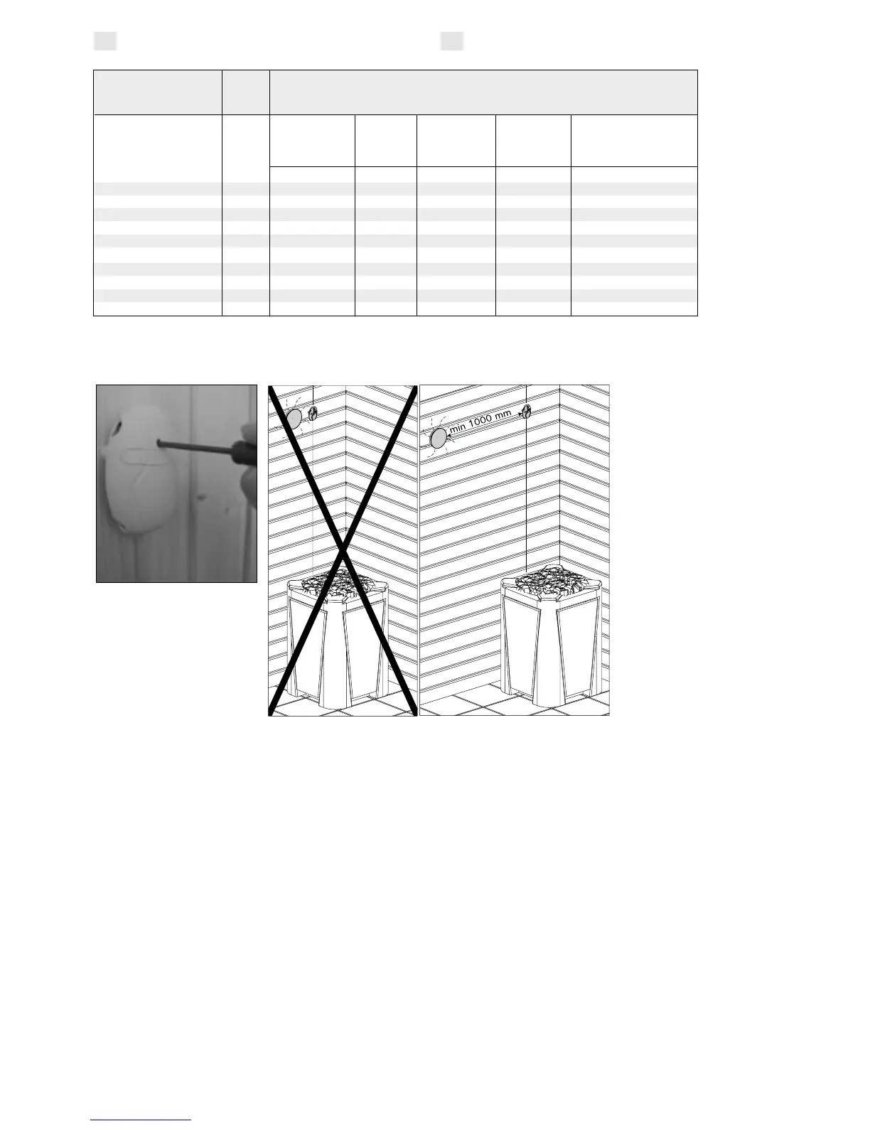
Installing the temperature
sensor near the
ventilation valves.
Montage des
Temperaturfühlers in der
Nähe des Lüftungsventils.
EN DE
Harvia Oy
PL 12
40951 Muurame
Finland
www.harvia.fi
 Loading...