5
Installation of the control unit (C90, C150)
and sensors (KIP45E–KIP90E)
Install the control unit in a dry place outside the sauna
room at the height of about 170 cm. The control unit
includes detailed instructions for fastening the unit on
the wall.
Install the temperature sensor on the wall of the
sauna room above the heater. It should be
installed on the lateral centre line of the heater,
100 mm down-wards from the ceiling. See fig. 5.
Electric heater insulation resistance
When performing the final inspection of the electrical
installations, a ”leakage” may be detected when
measuring the heater’s insulation resistance. The
reason for this is that the insulating material of the
heating resistors has absorbed moisture from the air
Anschluß des Steuergerätes (C90, C150)
und der Fühler (KIP45E–KIP90E)
Das Steuergerät wird in einem trockenen Raum
außerhalb der Saunakabine in etwa 170 cm Höhe
angebracht. In Verbindung mit dem Steuergerät
werden genauere Anweisungen zu dessen Befesti-
gung an der Wand gegeben.
Der Temperaturfühler wird an der Saunawand oberhalb des
Saunaofens, 100 mm unterhalb der Decke auf der Achse in
Breitenrichtung des Saunaofens angefracht. Siehe Abb. 5.
Isolationswiderstand des Elektrosaunaofens
Bei der Endkontrolle der Elektroinstallationen kann bei
der Messung des Isolationswiderstandes ein “Leck”
auftreten, was darauf zurückzuführen ist, daß
Feuchtigkeit aus der Luft in das Isolationsmaterial der
Heizwiderstände eingetreten ist (bei Lagerung und
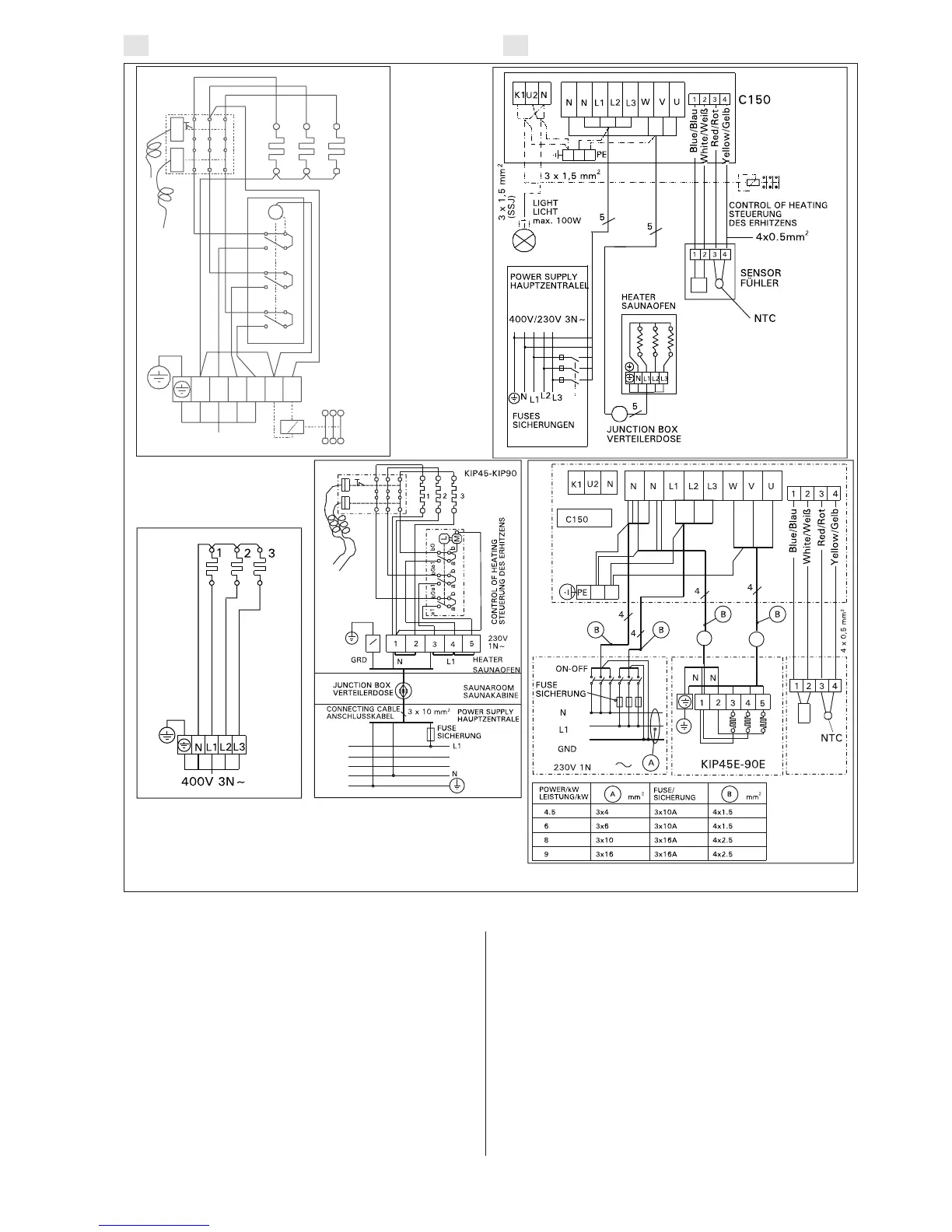
Figure 6. Electrical connections of heater
Abbildung 6. Elektroanschlüsse des Saunaofens
EN DE
400V 3N~
123
M
N
L1 L2
L3 N P
a1
a1
a1
b0
b
b0
b0
b
b
a
a
a
CONTROL OF HEATING
STEUERUNG DES ERHITZENS
KIP 45-90
KIP45E-KIP90E