4
Mains Connection
Due to thermal embrittlement, the use of PVC-
insulated wire as the connection cable of the heater is
forbidden.
The heater may only be connected to the electrical
network in accordance with the current regulations
by an authorised, professional electrician. The
heater is semistationarily connected to the junction
box on the sauna wall. The connection cable must be
of rubber cable type H07RN-F or its equivalent. In the
lower part of the heater there is a permanently
installed control unit (KIP45–KIP80). In addition to a
mains connector, the control centre is equipped with
extra connectors which enable the following
additional connections:
a) an indicator light above the steam room (see the
connection diagram). Cross-section of the
connection cable (see Table 1).
b) Locking of electrical heating with the heater (see
connection diagram).
The control cable of the electrical heating is
connected directly to the junction box, and from
there to the terminal strip by a rubber cable with
the thickness of a connection cable.
NOTE! The heater provides a voltage control
(230V) from the P and M connectors.
The KIP-E models require separate control centre C90/
C150 (C150VKK).
Elektroanschlüße
ACHTUNG! PVC-isolierte Kabel dürfen wegen ihrer
schlechten Hitzebeständigkeit nicht als Anschluß-
kabel des Saunaofens verwendet werden.
Der Anschluß des Saunaofens ans Stromnetz darf
nur von einem zugelassenen Elektromonteur unter
Beachtung der gültigen Vorschriften ausgeführt
werden. Der Saunaofen wird halbfest an die
Klemmdose an der Saunawand befestigt. Als
Anschlußkabel wird ein Gummikabel vom Typ
H07RN-F oder ein entsprechendes Kabel verwendet.
Am Unterteil des Saunaofens ist eine fest eingebaute
Steuerzentrale konstruiert. (KIP45-KIP80).
Außer dem Netzanschluss ist die Steuerzentrale
mit zusätzlichen Anschlüssen ausgestattet, die
folgende Anschlussmöglichkeiten bieten:
a) Kontrolllampe außerhalb der Saunakabine
(s. Schaltplan). Querschnitt des Anschlusskabels
(s. Tabelle 1).
b) Steuerung der Elektroheizung für den Saunaofen
(s. Schaltplan). Das Steuerungskabel für die
Elektroheizung wird direkt zur Klemmdose des
Saunaofens gelegt, und von dort aus direkt mit
einem Gummikabel der gleichen Stärke weiter
zur Klemmleiste des Saunaofens gelegt.
Achtung! Der Saunaofen gibt von einer P- und
M-Klemme eine Spannungssteuerung (230V)
KIP-E Modelle benötigen eine zusätzliche Steuerzentrale
C90/C150 (C150VKK).
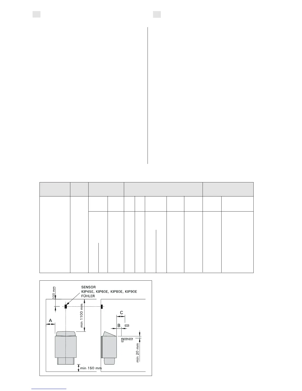
Figure 5. Safety distances from the heater
Abbildung 5. Sicherheitsmindestabstände des
Saunaofens
Table 1.
Tabell 1.
min max min
m
3
m
3
mm
KIP45/KIP45E 4,5 3 6 1900 35 20 35 100 1100 150 5 x 1,5 3 x 10
KIP60/KIP60E 6,0 5 8 1900 50 30 50 120 1100 150 5 x 1,5 3 x 10
KIP80/KIP80E 8,0 7 12 1900 100 30 80 150 1100 150 5 x 2,5 3 x 16
KIP90E 9,0 8 14 1900 120 40 100 150 1100 150 5 x 2,5 3 x 16
Heater Output Sauna room Min. distance from heater Connection cable/Fuses
Ofen Leistung Saunakabine Min. Abstand des Ofen Anschlußkabel/Sicherungen
kW
400V3N~
mm
2
*)
**)
A
mm
C
mm
B
mm
KIP-E
Cubic. vol.
Rauminhalt
Height
Höhe
To ceiling
zur Decke
To floor
zum Boden
Fuses
Sicherung
A
*) from front to upper platform
**) from side to wall
*) von der Vorderfläche zur oberen Bank
**) von der Seitenfläche zur Wand
Widht/Breite
41 cm
Depht/Tiefe
28 cm
Height/Höhe
60 cm
Weight/Gewicht
16 kg
Stones/Steine
max.
25 kg
EN
DE
 Loading...